Problem Statement
We partnered with the Seven Hills Foundation out of Groton to develop an assistive way to switch adapt a hose. They received raised garden beds to allow for patients to be able to garden; however, they did not have a way for the residents to water the garden.
Engineering Goal
Our engineering goal was to develop an assistive, switch-adapted watering system for raised garden beds at the Seven Hills Foundation in Groton. This system aims to establish a clear cause-and-effect relationship for users: pressing a button activates the water flow. The primary challenge was to integrate a reliable water control mechanism with user-friendly assistive technology, ensuring that residents can independently water their gardens and engage in therapeutic activities.
Current Approach
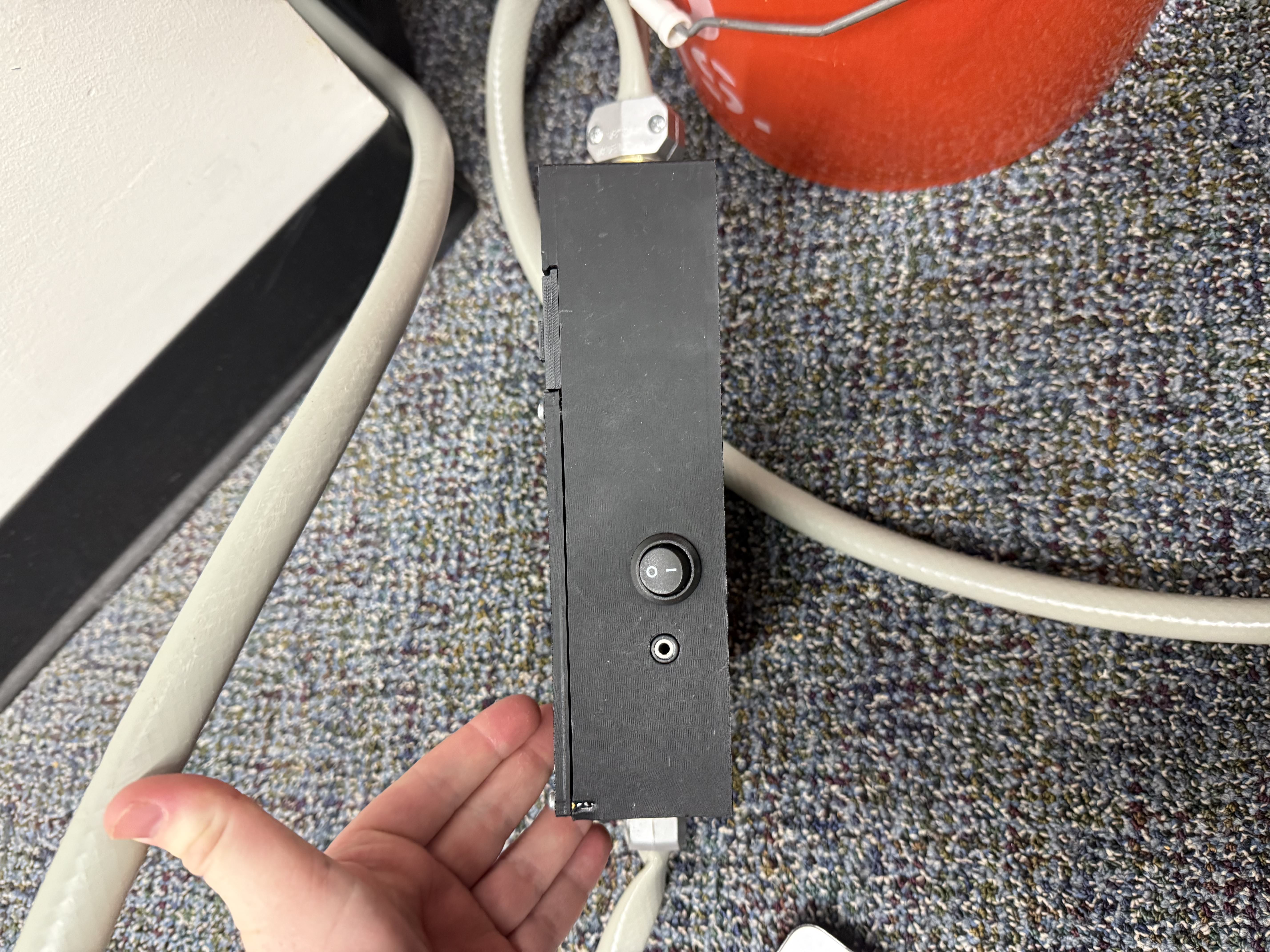
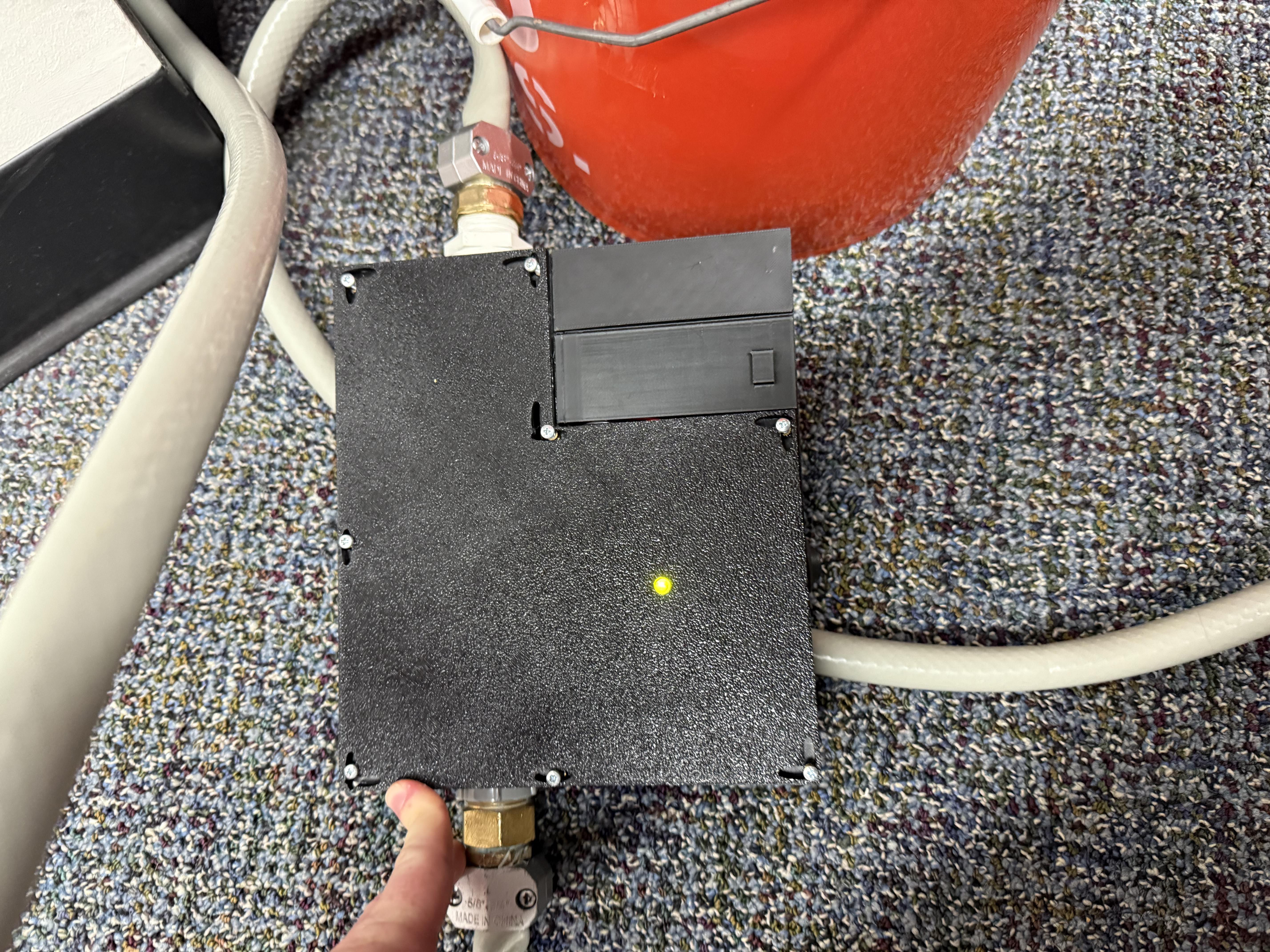
Our current approach to assembling the "Watering Point" system involves bringing together various components to create a functional device. We begin by preparing the structural housing, which includes several custom 3D-printed parts: the main body, the lid, and the battery compartment. Once these elements are ready, we integrate M3-sized threaded inserts into specific locations within the housing. A central aspect of our design is the solenoid valve, which is critical for controlling water flow. We carefully assemble this valve system, attaching specialized adapters to its ends using sealing compounds to ensure integrity. Both the input and output sides of this mechanism are then built out, incorporating various connectors and piping sections, which are securely joined using appropriate bonding agents. These assemblies are then carefully positioned within the fabricated housing. To safeguard the internal electronics, we implement a sealed pass-through for the necessary wiring, designed to isolate sensitive components from potential moisture. We also secure the solenoid within its compartment to prevent movement. User interface elements are then integrated, including a primary connection point for external controls, which is secured within the housing. For power management, a magnetic latching system is incorporated into the battery access point. Finally, the electronic heart of the system is wired. This involves connecting the Arduino Nano, a Motor Controller, a primary power switch, and the 9-Volt Battery Connector. Wiring is meticulously routed, and the power switch is installed into its designated exterior opening. The system's status indicator, an LED, is also placed within the lid. The final step in assembly involves closing the housing with the lid and securing it with M3 bolts.