|
Linear Algebra
I Section E01, E'00 |
MINI PROJECT |
Back to
|
|---|


| 2. Electrical Circuits |
|---|
|
Linear Algebra
I Section E01, E'00 |
MINI PROJECT |
Back to
|
|---|
| 2. Electrical Circuits |
|---|
This mini project is devoted to one particular application of linear systems. It is supposed to be a good chance to know that even with the few tool you have acquired so far, you can solve - or tackle - this engineering problems.
Suppose we have an electric network such as the one pictured in Fig.1. The currents and the voltage drops around the network satisfy Kirchhoff's first and second laws:
A typical application of these laws is when we are given the voltage of the electromotive force (usually, a battery or a generator) and the resistance of the resistors and we are asked to compute the currents.
For each element of a circuit, we have to choose a positive direction for measuring the current through that element. The choice is indicated by arrows. For the voltage source we choose as positive direction the direction from the negative sign to the positive sign. The voltage source adds voltage; hence, the voltage change is positive, whereas the voltage change through the resistors is negative due to voltage dropping.
For example, assume that for the circuit in Fig.1, the voltage of the battery is E = 6 V and the resistance are R1 = 2, R2 = 2, R3 = 1 Ohms each. What are the currents i1, i2, i3?
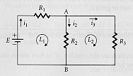 Fig.1
Fig.1
By the first law, we have i1 - i2 - i3 = 0 from branch point A. Applying the second law to loops L1 and L2 yields, that 6 - i1R1 - i2R2 = 0 and i3R3 - i2R2 = 0, hence:
i1 - i2 - i3 = 0and by Gauss elimination we easily get: i1 = 2.25, i2 = 0.75, and i3 = 1.5 A.
2i1 + 2i2 = 6
-2i2 + i3 = 0
1. Finding Currents
Determine the unknown currents in the circuit shown in Fig.2.
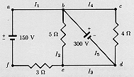 Fig.2
Fig.2
2. Finding Unknowns
Determine the unknowns in the circuit shown in Fig.3.
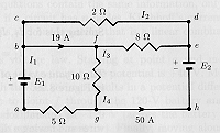 Fig.3
Fig.3
3. The Proof
For the circuit in Fig.4,
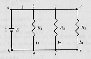 Fig.4
Fig.4
show that
I1 = I(R/R1),
I2 = I(R/R2),
I3 = I(R/R3),
where 1/R = 1/R1 + 1/R2 + 1/R3.
 The Course Text, Sections 1.5 and
8.2.
The Course Text, Sections 1.5 and
8.2.

[ Back to COURSE MINI PROJECTS ]
[ Project 1 | Project 2 | Project 3 | Project 4 | Project 5 ]
[ Course Information | Home Work Assignments | Mini Projects | Maple Exercises | What's New? ]
![[WPI HomePage]](/Buttons/seal.gif)
|
Department of Mathematical Sciences | Back to Vadim Yakovlev's Professional Page |
|---|