STEM I (Science, Technology, Engineering, and Math) is the
first component of our Science and Technical Writing course taught by Dr. Crowthers. Running
from the start of the school year through mid-February, this course
focuses on exploring a scientific field of our interest through
an independent research project. Throughout the process, we develop
skills in scientific research and engineering design while learning
the importance of time management. The course also
emphasizes technical communication, requiring us to write a variety of
professional documents such as grant proposals and a thesis.
Below is a chart that provides a brief overview of my project.
Trouble viewing PDF? Click here.
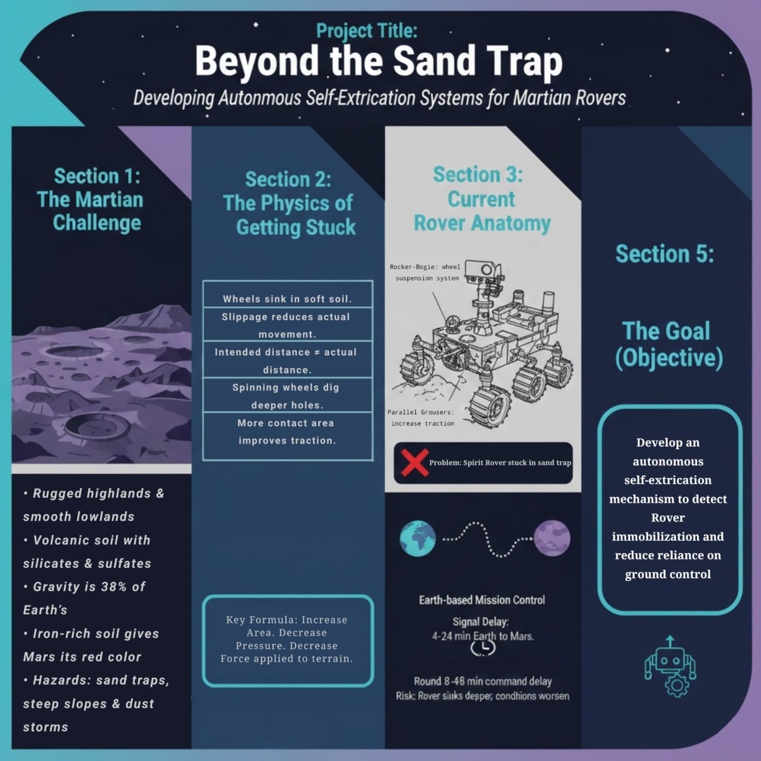
A Novel Self-Extricating Mechanism for Martian Planetary Exploration Rovers
Wheels that can autonomously increase their contact area with a surface can decrease slippage and sinkage on granular terrain, making Martian planetary rovers independent of ground control in an embedding event.
Abstract
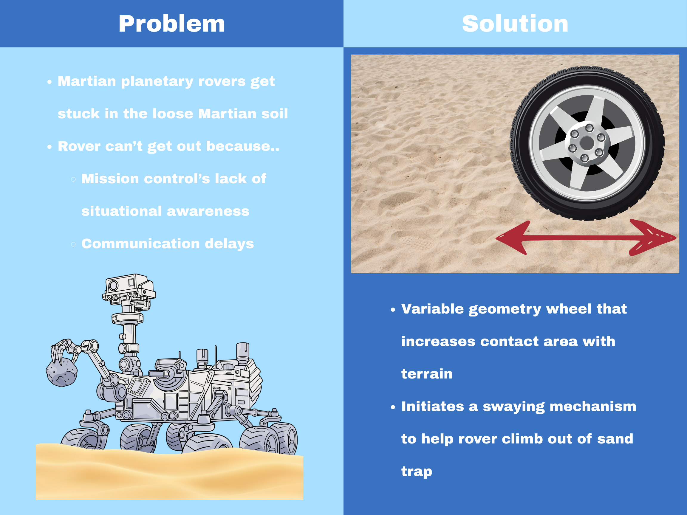
The goal of this research project is to make planetary rovers independent of mission control in the event that they are
stuck in the loose Martian terrain. The design does this by introducing a variable geometry wheel for rovers, that essentially
uses live data from the wheel’s sinkage and slippage to adjust the wheel’s width and force applied on the terrain. This improves
the vehicle’s traction on the terrain, allowing it to move out of a sand trap. A low fidelity prototype of this design was created to
verify if the locomotion performance truly improves when the contact area between the wheel and the terrain is increased. This prototype
design passively changed its geometry with the terrain with the use of a flexible material for its circumferential surface. This design was
tested on sandy terrain where the sinkage and slippage of the vehicle was measured. The results from the prototype were then compared to the
slippage and sinkage of a vehicle with rigid wheels to mimic traditional rover wheels. The prototype design only showed a slippage of 48% while
the rigid wheel had a slippage of 100%. Furthermore, the rigid wheel sunk 11mm into the sand during one of the tests. This experiment shows that
flexible wheels work better than rigid wheels on granular terrain, helping lay the foundation for a more active and autonomous design. Prior to creating
the higher fidelity prototype, a load simulation was run on Fusion 360 to determine which material would deform the best but also return to
its normal shape after withstanding some amount of load. A CAD model of the wheel design was tested with 20 different materials, where each material's displacement,
yield strength and safety factor was measured when subject to 200N of load. Using the information gathered in these test, it was determined that Iron, Malleable would
be the best material for our purposes. Using the information collected a more detailed wheel prototype will be made and tested.
If you are interested in learning more, click here to view my Research Proposal
Engineering Need
Planetary rovers on the Martian Surface often get stuck in the loose Martian soil.
In the event a rover is embedded in the terrain of another planet, the only method of extracting
it is through maneuvers controlled by ground-control on Earth, which usually does not have a high success rate.
Engineering Goal
The objective of this project is to create an autonomous self-extrication method for planetary rovers
that is applicable in various states of embedding in the Martian soil, ensuring that the rover isn’t completely
reliant on ground-control to get itself out of these situations.
Data and Analysis
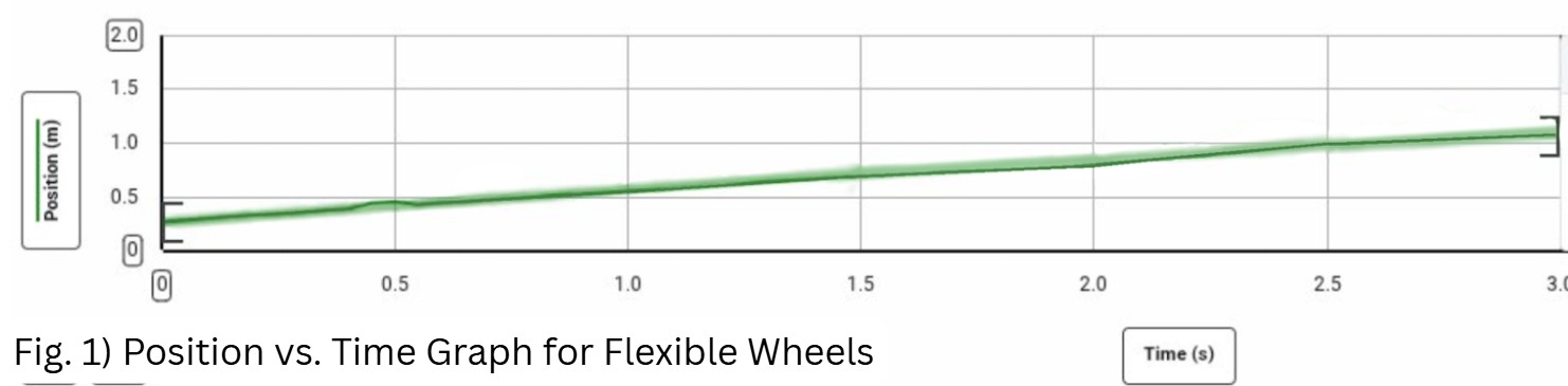
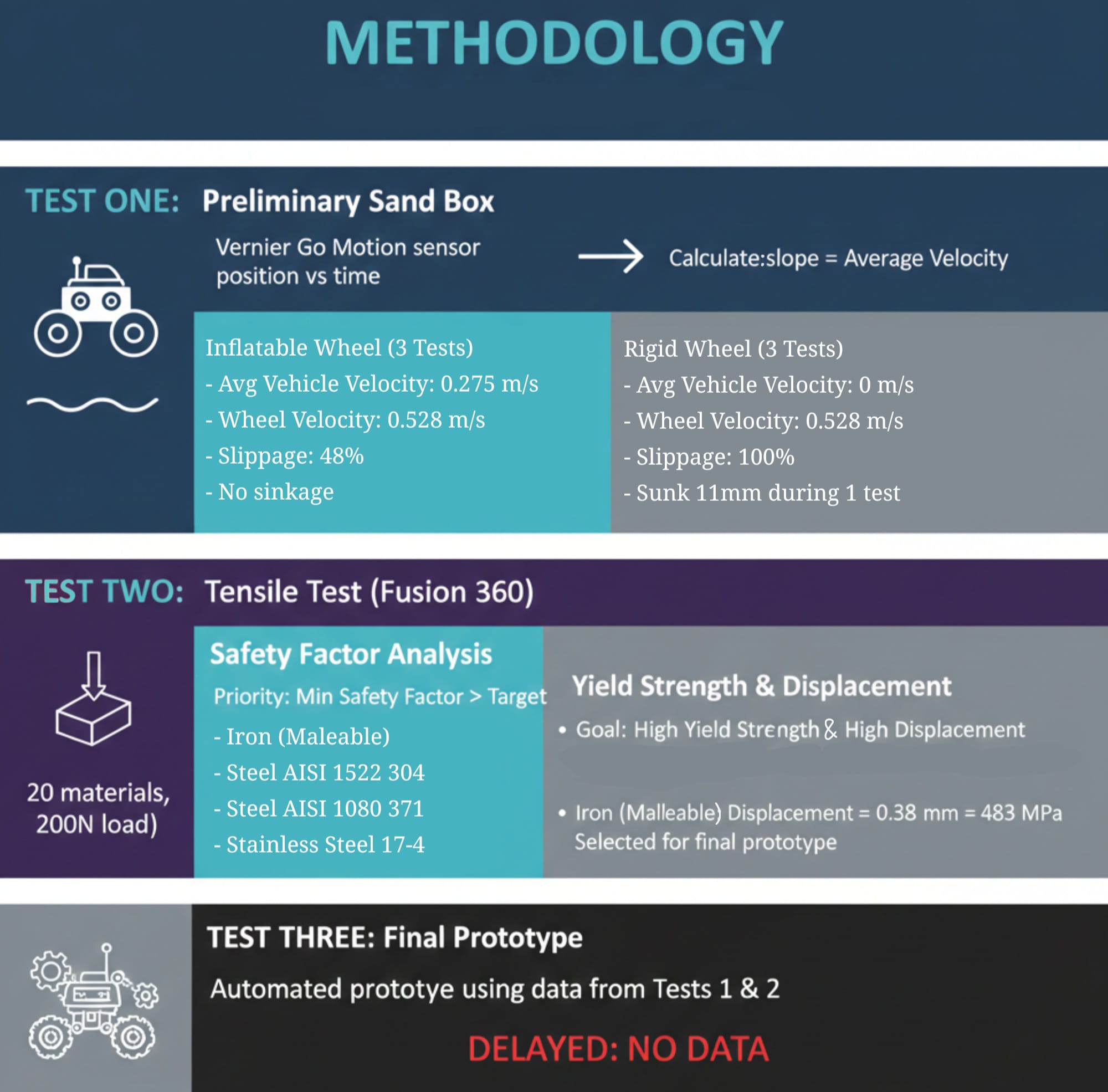
During the preliminary sand box test, a Vernier Go Motion sensor was used to generate position vs time graphs of a robot with the
flexible and rigid wheel. Then the slope was calculated to get the average vehicle's velocity.The rover with the inflatable wheel was tested 3 times, generating 3 different position vs time graphs.
Fig 1. is an example of one of these graphs. These gave the average vehicle velocity of 0.275m/s and the wheel’s rotational
velocity of 0.528 m/s. The inflatable wheels had a slippage of 48%, but there were no incidents of sinkage in any of the 3 tests.
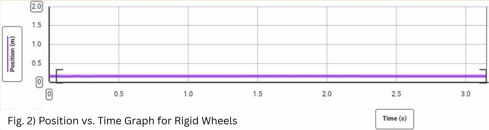
The rover with the rigid wheel was also tested 3 times on the same testbed. Fig 5. is an example of one of
the 3 position vs time graphs generated during these tests. The wheel itself had a rotational velocity of 0.31 m/s;
however, it didn’t move forward when placed on the test bed, which means it has a 100% slippage. Furthermore, the wheel
also sunk 11mm into the sand during one of the tests.
The tensile test was done with 20 materials using Fusion 360 to see how each material would respond to a load of 200N.
For each material being tested, its safety factor, yield strength, and maximum displacement were measured.
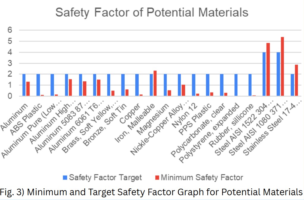
Fig 3. shows the Safety Factor Target and the Minimum Safety Factor for each of the 20 materials.
To ensure the material would break or permanently deform under the load, the minimum safety factor would
have to be higher than the target safety factor. This was the first priority when looking for materials to make
the circumferential surface of the wheel. Out of the 20 materials, only 4 met this criterion. These materials were:
Iron (Malleable), Steel AISI 1522 304, Steel AISI 1080 371, Stainless Steel 17-4.
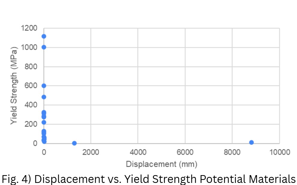
Fig 4. Shows the yield strength vs. displacement for each material. The ideal material would have a high yield
strength and a high displacement because it would ensure that the wheel deforms the most with the terrain while
also ensuring it only experiences elastic deformation. Since none of the 20 materials exhibited these characteristics,
the yield strength and displacement of the four materials that had greater minimum safety factors than the target were compared.
These four materials had similar yield strengths; thus, their displacements were compared instead. Iron (Malleable) had a displacement
of 0.328 millimeters, which was the greatest displacement out of the four materials and a yield strength of 483 MPa. This will be used
in the final prototype.