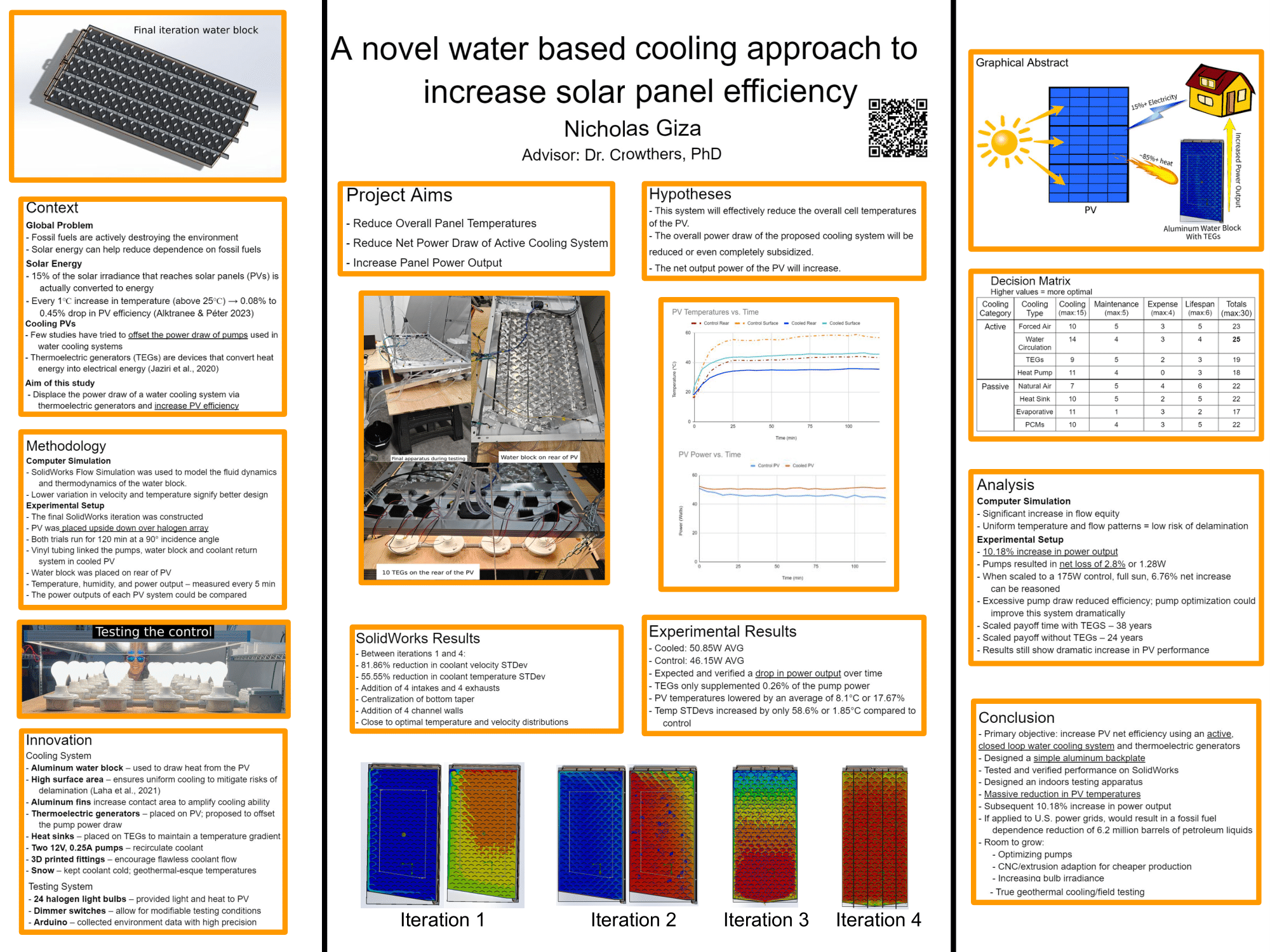
STEM I
STEM 1 is a course entirely dedicated to the completion of a 5-6
month long research project. This project focus in on several
different general areas including computer science, biology,
engineering and other genres of scientific research. During the start
of the year, brainstorming takes place, defining possible problems to
address in this project. Once ideas are solidified, the research
process begins, lasting until December allowing for the development
of well rounded understandings of the research topic. Throughout this
process, proper documentation, citation and project development
practices. By the end of December, preliminary data is taken, results
are presented at December fair, and a well earned break is taken.
Coming into January, STEM 1 picks up and data is due. In the final
push, it is common for people to pull long nights to get their final
data. Once data is collected and the thesis written, the only step
left in STEM 1 is project presentation at February fair. STEM 1 is a
truly amazing course, providing significant research opportunity to
its students. Below are excerpts from the thesis I wrote regarding my
project. The full thesis can be found on
THIS PAGE.
A novel water based cooling approach to increase solar panel
efficiency
The purpose of this project was to put forth an economical,
highly effective photovoltaic/solar(PV) water cooling solution. This
comes as excessive PV temperatures is one of the largest detriments
to solar panel output/efficiency. The solution I put forth uses a
thin, 5 channel aluminum back-plate to circulate cold water through
the rear of a PV, cooling the PV via conduction. After thoroughly
designing and testing this water-block in SolidWorks Flow Simulation,
I designed a method for testing the apparatus indoors. In addition to
this water-block, I used thermoelectric generators with the intention
of subsidizing the power draw of recirculation pumps. Following
testing, results suggest a 10.18% increase in efficiency before pumps
and thermoelectric generators were considered and when scaled to the
full radiant energy available by the sun, the net efficiency/power
output increase was 6.76%, a value which is highly meaningful to the
market of clean energy.
Abstract
Graphical Abstract

As the world
becomes increasingly more dependent on its power grids, it has
simultaneously become more dependent on fossil fuels. To offset this
harmful reliance, photovoltaic solar panels (PVs), can be used to
cleanly and renewably produce electricity. One major flaw that
plagues solar energy is the fact that PVs lose significant amounts of
efficiency when hot. In fact, for every 1℃ increase in temperature
(above 25℃), there is a 0.08% to 0.45% drop in power output
efficiency (Alktranee & Péter, 2023). With normal operating
temperatures as high as 70℃ (Akal & Türk, 2022), this is
detrimental to electrical output. In response, this study produced a
closed-loop, water-cooling system powered by thermoelectric
generators (TEGs) to reduce solar panel temperatures and increase
performance. Two forms of apparatus were designed and analyzed.
Finite element analysis in SolidWorks simulated coolant flow and
served as a visual representation for to-scale design. FEM results
were tested in a physical environment where one control PV and one
water-cooled PV-TEG were set up under a 1728W array of halogen light
bulbs. In testing, SolidWorks Flow Simulations suggested relatively
equitable coolant flow rates, supported with f-tests. Physical
testing suggested a 4.70W or 10.18% average increase in
efficiency/power output; enough power, when scaled to a fully powered
PV, to support the cooling system. With this in mind, entire solar
array cooling systems can be designed that scale this system
accordingly. The implications of this highly functional, closed-loop
cooling system for PVs provide immense potential for a more
sustainable planet.
Problem Statement
Objective
Solar panels lose a
dramatic amount of efficiency when operating at higher temperatures.
Cooling systems are needed to maximize system output.
I aimed to design a low
cost, simple and effective cooling system to reduce solar panel
temperatures and in turn, increase panel efficiency.
Background
As populations rise and
technology advances, there is a continuous need for more energy.
Unfortunately, that often means using more fossil fuels to offset the
increased global power draw. Fossil fuels are actively destroying the
environment through the emission of greenhouse gasses including carbon
dioxide. As a result, it is paramount to our planet’s well-being that
advances be made to increase the output of renewable energy sources,
such as solar, to reduce dependence on fossil fuels. Solar energy is a
form of clean, renewable energy that uses photovoltaic cells to
convert solar radiation into electrical energy. This process releases
no greenhouse gasses and is a popular option for those looking to
reduce their dependence on fossil fuels and, consequently, reduce
their carbon footprint.
Only about 15% of the solar
irradiance that reaches solar panels is converted to energy; the rest
is lost as heat (Salehi et al., 2021). As the solar panels heat up,
they lose a significant magnitude of power output. In fact, for every
1℃ increase in temperature (above 25℃), there is a 0.08 to 0.45
percent drop in power output efficiency (Alktranee & Péter, 2023).
With normal operating temperatures as high as 70℃, this is detrimental
to electrical output (Akal & Türk, 2022). Thus, high operating
temperatures are a significant threat to the efficiency of PVs. Panels
operate at the lowest possible temperatures to produce the most
electricity. If more energy can be harvested by solar, less fossil
fuels must be burned to support power grids worldwide.
Several studies have been
conducted to address solar panel cooling, and they can be divided into
two main categories: active cooling and passive cooling. Active
cooling requires an input of electricity, whereas passive cooling does
not. Previous studies have utilized various cooling methods including
water cooling (Chanphavong et al., 2022; Terashima et al., 2023;
Zubeer & Ali, 2022), nanofluids, forced and passive air circulation
(Rahman et al., 2023), thermoelectric modules (Salehi et al., 2021),
heat sinks, and many others. While most studies with active
water-cooling solutions use pumps to circulate coolant, few consider
the associated power draws. Furthermore, fewer try to subsidize this
power draw. A significant knowledge gap arises when thermoelectric
generators are put into consideration. Thermoelectric generators
convert heat flux (temperature differences) into electricity via the
Seebeck effect (Jaziri et al., 2020). There is a clear lack of
knowledge regarding how thermoelectric generators can work in
conjunction with photovoltaic (PV) water cooling systems.
Researchers based in Laos,
led by Lemthong Chanphavong, created an active cooling system
consisting of a thin layer of continuously flowing water over the
surface of a panel to keep it cool. Two solar panels were set up. One
had no specialized cooling system, while the other had a custom
water-cooling system. This system consisted of a few PVC pipes
oriented so that a DC pump could transport water to the top of the
panel. As the water left a distribution PVC pipe, it formed a thin,
flowing film over the surface. During testing, climate conditions
(ambient temperatures, relative humidity, wind speeds, and solar
irradiances) as well as electrical outputs of the panels and panel
surface temperatures were measured every thirty minutes. Results
suggest an approximate exergy (usable energy) efficiency increase of
9.8% as a direct result of lowering panel temperatures by as much as
29.2℃ (Chanphavong et al., 2022).
A study in Japan, led by
Terashima et al. (2023), aimed to compare two different water-based
solar PV/T or photovoltaic thermal systems using both a CIS (copper,
indium, selenium) and a m-Si (monocrystalline silicon) panel type. A
water block was placed on the rear side of the panel, where flow rates
were controlled to change the output temperature of the coolant. These
output temperatures corresponded to two use cases: space heating and
cooling. Instead of a traditional pumping method, a
decompression-boiling heat collector was used, boasting lower power
draw, and higher efficiency. Results suggest that the CIS PV/T system
was able to convert 73.5% of the solar energy at a 40℃ water output
and 45.9% of the solar energy at a 60℃ water output, whereas the m-Si
panel type, in the same conditions, showed to operate at a
dramatically lower efficiency (Terashima et al., 2023).
A Malaysian research group,
led by Noor Muhammad Abd Rahman, utilized a custom cooling system
consisting of a customized plenum and specially designed aluminum heat
sinks to transport cool air from a heat pump through the back of the
panel and back down to the heat pump where the heat can be recycled.
The findings suggest an impressive 12.35% increase in panel efficiency
(as compared to the nominal operating cell temperatures, NOCT) and a
comparatively low, 17% decrease from the standard testing conditions
(STC) (Rahman et al., 2023).
A research group, led by
Salehi et al. (2021), studied the use of thermoelectric modules to
pump heat from the rear of a solar panel to corresponding anodized
aluminum heat sinks. This system reduced the overall temperature of
the panel by an average of 10.04℃, allowing for a 10.50% increase in
energy output (Salehi et al., 2021).
Similarly, another group
researched the use of thermoelectric generators in improving solar
efficiency by reducing panel temperatures and in turn producing
electricity through the Seebeck effect. The Seebeck effect is a
natural phenomenon that states that whenever there is a temperature
difference between two different electrical semiconductors/conductors,
a voltage is produced between those two materials. Thirty
thermoelectric generators, fitted with aluminum heat sinks, were put
on the back of a solar panel to reduce panel temps and increase output
electricity. Results suggest an average of 8.4% more electrical energy
was produced by the TEG than the standard PVs (Akal & Türk, 2022).
According to research done
by a group from the Indian Institute of Technology, operating
temperatures of photovoltaic cells are crucial to their longevity.
When the temperatures within the cells vary too significantly,
delamination can occur, resulting in the deterioration and shortened
lifespan of PV cells. To model this situation, a conduction-based
thermal model was designed to analyze the thermal interactions between
a PV with and without a rear-mounted heatsink. Results suggest that
hotspots, which cause delamination, tend to occur on the outer edges
of the PV. With the addition of a simple, passive cooling system, this
model was able to find an approximate 1% increase in PV efficiency
(Laha et al., 2021).
The proposed design works
to include concepts from each of these studies including
conduction-based water-cooling and the use of thermoelectric modules
to effectively cool a PV system and in doing so, increase PV power
output. The major reference designs are from Akal & Türk (2022) and
Terashima et al. (2023) as both have influenced the design and methods
of this project.
Procedure
Several studies have
examined the effectiveness of PV water cooling and have generally
found water cooling systems highly effective. Based on these studies,
two categories of water cooling can be identified: closed loop and
open loop. Closed loop water cooling systems are sealed off and, if
built properly, will not lose an impactful quantity of coolant through
normal operation. These systems require the water to be cooled after
passing through the heat source to return and efficiently draw heat
from a PV (Chanphavong et al., 2022; Terashima et al., 2023). If the
coolant returns hot, it will have a weaker cooling effect as justified
by the specific heat formula. Open loop cooling, on the other hand,
does not necessarily reuse the coolant and often requires a constant
water source and a method to dispose of used coolant. If used coolant
is recirculated, it is generally more at risk to factors such as
evaporation or contamination from outside elements such as dust or
other debris (Zubeer & Ali, 2022; Alktranee & Péter, 2023).
Consequently, open loop cooling systems often have a larger resource
and maintenance requirement. With this in mind, a closed loop PV water
cooling system was chosen for use in the proposed apparatus to take
advantage of the cooling abilities of water while not requiring a
considerable amount of maintenance or resource input.
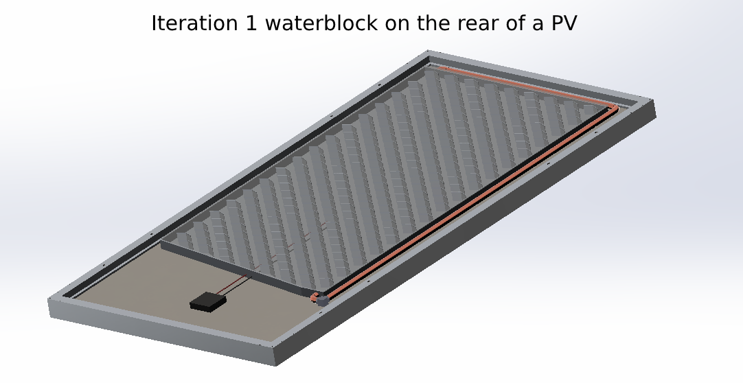
To contain the water and
effectively transport heat, an aluminum water block was used. Aluminum
was chosen because it has a high specific heat capacity of 0.89 J/g℃
and is able to effectively transfer heat from the PV to the coolant
(A. Powell, personal communication, November 7, 2023). A high surface
contact area between the PV and water block is necessary to ensure
consistent cooling across the PV to mitigate risks of delamination
(Laha et al., 2021). In this study, an aluminum container spans the
rear of a PV with tapering towards the water recirculation port(s) to
direct coolant in the proper outflow direction. Other materials,
including copper and stainless steel, were considered for use in the
backplate but were deemed to be too expensive for practical
application.
Water recirculation
occurred with the help of a small aquarium pump and flexible vinyl
tubing. After flowing through the block, water returns to the top
where it flows back through. While the water flows through the
aluminum container, it flows around angled aluminum fins which aid in
the heat distribution into the coolant (Terashima et al., 2023; Zubeer
& Ali, 2022). Using angled fins was hypothesized to allow for more
effective heat transfer while promoting smooth coolant flow. The top
of the block was sealed with another sheet of aluminum.
Pumps used in water
cooling systems can draw somewhere in the range of 12 volts and 3 amps
(Chanphavong et al., 2022). Resultantly, using PVs to power their own
cooling reduces their net power output. The use of thermoelectric
generators is proposed to offset this power draw. Thermoelectric
generators, otherwise known as Peltier modules in the Seebeck mode,
are devices that convert heat energy into electrical energy (Jaziri et
al., 2020). In this model, 10 TEGs were placed on the rear of the
panel, above the water block. The power output of these TEGs could
then be wired directly to the power input of the recirculation pump so
that the TEGs supply or supplement the pump’s power draw. Heat sinks
were placed on the cold side of the TEGs to help maintain a
temperature contrast between the hot and cold sides of the TEGs. Data
from a previous study suggests that TEGs placed on the rear of a panel
can produce electricity and reduce panel temperatures (Akal & Türk,
2022). This same logic is applicable to the proposed apparatus and
were used to supplement the power for the recirculation pump. As the
temperatures of the PV lower, so will the output voltage of the TEG,
reducing the speed of the pump. A reduction in pump speed is
acceptable because once the panel is cooler, it requires less cooling
and lower coolant flow rates.
The aluminum backplate was
fixed to the rear of the panel, assuring full contact with the PV back
panel. The recirculation tubing was attached to the water block with
custom fittings and to barb fittings present on the pump. The TEGs
were fixed to the upper portion of the PV with the help of a silicon
thermal glue to aid in the transfer of heat from the PV to the TEGs.
The same glue was used to adhere aluminum heat sinks to the cold sides
of the TEGs (Alktranee & Péter, 2023). Once put together, the PV-TEG
(photovoltaic/thermoelectric generator system) was put into the
testing simulator for data collection.
To fully understand the
interactions between the flowing coolant and the PV, computer-based
flow simulations were conducted. SolidWorks Flow Simulation was used
to model the fluid dynamics and thermodynamics involved in the cooling
block. This software was not used to simulate any interactions within
the PV; it takes only an input heat from the aluminum plate (70
Celcius), which is adhered to the rear of the PV and simulates the
heat transfer from the plate, through the coolant and to the other
side of the water block.
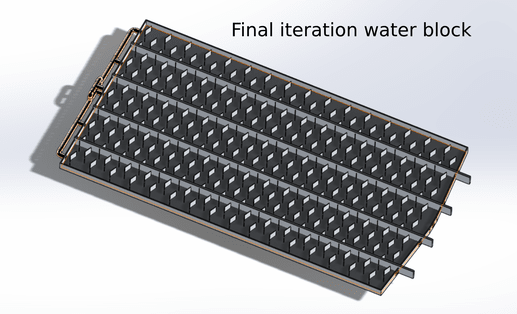
In the final iteration, the
coolant (water) enters the PV water block through 5 intake holes
positioned at the top and flows through a series of angled aluminum
fins until it is directed to 5 lower exit holes placed directly below
the intakes. At the intakes, the water enters at a flow rate
comparable to that of a small aquarium pump (240L/min divided amongst
the intakes). The bounds of the flow model end at the exit hole. In
addition, the mesh size (density of measuring points in the model) was
reduced from the maximum with minimal impact on model accuracy to cut
down on simulation duration (Laha et al., 2021).
The results of the model
include coolant pressure, water block pressure, coolant temperature,
water block wall temperature, water block fin temperature, coolant
velocity, and coolant turbulence. These factors were analyzed, and the
model adjusted to optimize the heat transfer from the PV backplate to
the coolant. The desired results of the flow simulation include
uniform coolant flow and temperature distribution to both remove heat
and prevent delamination (Laha et al., 2021).
In order to truly
understand the effectiveness of the proposed cooling system, it must
be tested in a physical environment. In response to outdoor
temperatures well below freezing during the testing period, the sun
was simulated indoors with an array of halogen light bulbs. A panel
was placed above this array to allow for heat and radiant energy from
the bulbs to travel upwards to the PV. A control group used this setup
without modification whereas the modified group was fitted with a
physical representation of the backplate discussed earlier.
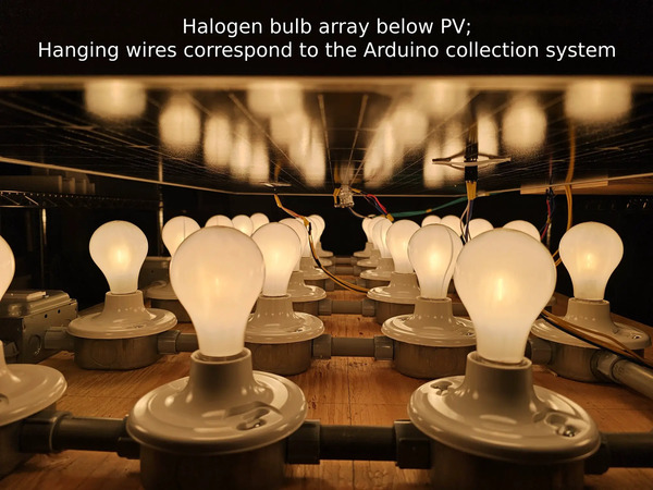
The solar simulator
consists of 24, 72W halogen light bulbs wired in parallel at 120V. The
array was put in a 6 by 4 light bulb format where every two rows of
four light bulbs (8 bulbs, 576W) were wired to 600W dimmer switches to
allow for variable light intensity. The dimmer switches were wired in
parallel to a power cord which was plugged into a 20A, 120V (2400W)
outlet. This design was produced with the help of Shaun Lindgren from
Lindgren Electric who advised on safe electricity practices and aided
in the overall wiring. In addition to power cables running through the
system, ground cables were run through each octagon box (the
containers below the bulb mounts) to ground all conductive elements of
the system. If any parts of the system become live, a short will trip
a circuit breaker and disconnect the electricity. Once operational, a
PV was placed above the lights where the radiant energy was converted
to electrical energy via the photovoltaic effect. With most of the
1728W of power provided to the bulbs, the rest of it is emitted as
radiant energy which travels to the surface of the PV. This system has
been engineered to be both safe and effective.
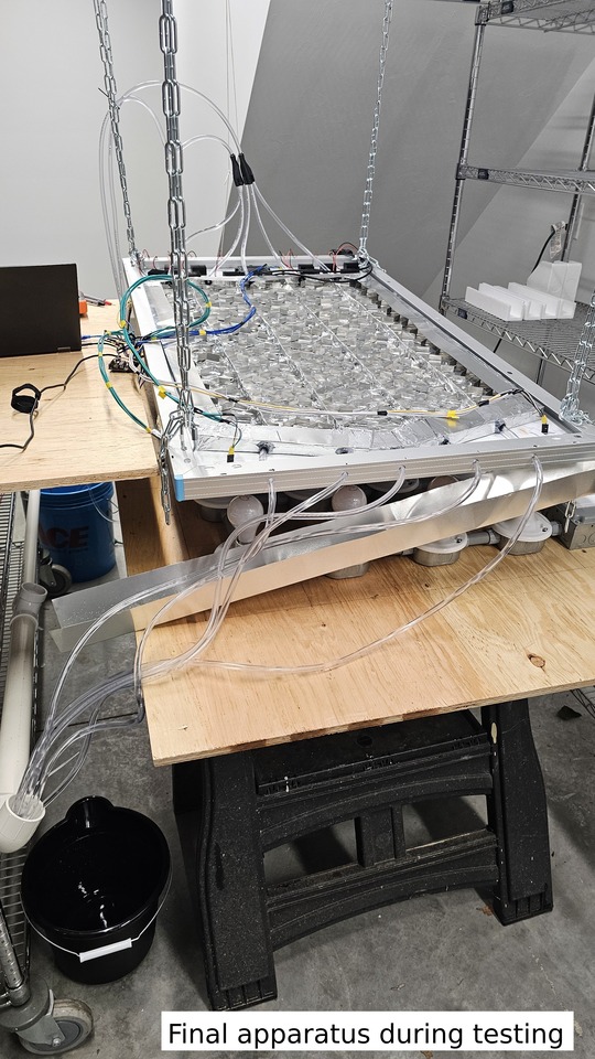
Once the lighting system
was set up, the water block was constructed and fitted to the rear of
the panel with one 3W pump sending coolant to the five intakes and
collecting it in a container to reuse. The coolant was cooled with
freshly collected snow, to simulate a somewhat extreme geothermal
cooling system. Above the water block, ten thermoelectric generators
were placed and fitted with their own heat sinks. The panel apparatus
was angled parallel to the lights to simulate a zero-degree
(perpendicular) angle of incidence. This angle of incidence correlates
to the maximum irradiance as is justified by the Cosine Law (Smith, N.
A., 2003).
Once positioned, the
Arduino data collection system was set up with 3 temperature probes on
the front glass of the PV, and three temperature probes on the rear.
Additionally, a light sensor was placed on the surface of the PV to
find the lux (lumens per meter) that hit the PV. These sensors
collected data every five minutes for the duration of the 120-minute
testing period. Additionally, every five minutes, the power outputs of
the PV and thermoelectric generators were measured and the power
consumption of the pump logged. The control group experienced all of
the same conditions and data collection methods with the exception of
thermoelectric and pump data collection as the control model had
neither.
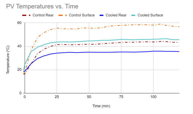
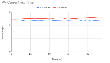
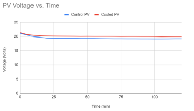
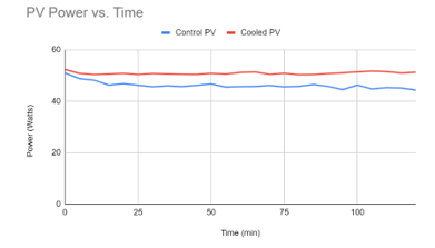
(Above) The first graph shows the differences in PV temperatures in
the physical testing. The second shows PV current over time of both
sides while the two subsequent graphs show voltage and power output
over time respectively. For more information regarding SolidWorks
results, see "Results" on the thesis linked on
THIS PAGE.
Analysis
The results of the
SolidWorks Flow Simulations signified significant improvement in
coolant flow patterns. When compared to the initial iteration, the
final iteration showed a 55.55% reduction in coolant temperature
standard deviation with an 81.86% reduction in coolant velocity
standard deviation. Both were proven significant with all p-values
less than 2.35E-76 when data was run with f-tests. F-tests were used
as they check for significant differences in variance which is just
the square root of standard deviation. This reduction in standard
deviations and consequently, variance, signifies significant
improvement in the uniformity of coolant flow and the homogeneity of
coolant temperatures. The uniformity of coolant velocity was targeted
to prevent dead zones and higher velocity flow areas. With more
uniform flow, more coolant leaves at roughly the same rate, preventing
portions of the coolant from staying in the water block longer than
other portions. Thus, the variance/standard deviation of the coolant
temperature reduced. Coolant at a more uniform temperature reinforces
uniform panel cooling, reducing temperatures while reducing the risk
of delamination. The results of the final design reflect this
rationale and provided sufficient evidence to move forward to justify
the construction of a physical model.
Over the course of
designing and executing the physical simulation, many design
challenges were overcome to build the simulator and water block
including frequent leaks at fluid flow junctions, the equalization
flow distribution and the creation of a lighting array in place of in
field testing. Solutions involved creating customized fittings for
coolant flow junctions, flow splitters and an array of 24, 72W halogen
light bulbs. With each challenge overcome, the design of the system
was optimized and improved considerably. Upon the completion of the
model, the simulator was run.
Following the end of the
trial period, it was observed that the cooled PV showed significant
improvements in temperature and power output from the control. With
coolant kept at roughly 12-13°C, the cooled PV showed a substantial
reduction in both surface and rear temperatures when compared to the
control. The resulting increase in power output was 10.18% higher than
that of the control, increasing the power output by 4.7W on average,
supported with paired t-tests for difference of mean with a p-value of
4.09E 15. The pumps used to circulate fluid in the system drew 6W,
resulting in a net decrease in efficiency of 2.8% or 1.28W. In the
tested model, the pump was not subsidized by increased output. With a
10.18% increase in efficiency using the cooling system, a 175W solar
panel can easily subsidize the draw of the pump. With the achieved
efficiency increase, a control group with an output of 175W normal
output, for example, would likely find a net increase of 11.82W or
6.76% when fitted with this cooling system.
The relatively low power
output achieved from the 175W PVs in both the control and cooled
system comes as the irradiation levels of the Halogen bulbs used in
the simulation were not as high as those of the sun in STC, which is
roughly 1000W/m2 (Rahman et al., 2023). Additionally, the power output
of a PV depends on the wavelength of light which was not identically
simulated by the halogen bulbs, further justifying the relatively low
output of both PVs (Ramkiran et al., 2020). Even so, when scaled, the
net performance increases found in this study represent a major
improvement over the scaled control.
The objectives of this
study were almost unanimously achieved. The temperatures of the PV
were effectively lowered by an average of 8.1°C or 17.67%. The reduction in glass temperature was supported with a paired
t-test for difference of mean with a p-value of 5.59E 11 and the
reduction in the rear temperature was supported with a p-value of
5.62E 11. This reduction in temperature is reasoned as the primary
cause of the observed increase in PV power output. Even though the
cooled system was unable to produce a net power increase, when scaled
it was found that this system could easily achieve a net power
increase assuming a similar increase in efficiency.
As far as equitable
temperature distributions across the cooled PV, temperature standard
deviation was increased by roughly 58.6% or 1.85°C as compared to the
control. The temperatures recorded from both the back and front of the
control PV had an average standard deviation of 3.16°C whereas the
cooled PV temperatures had a standard deviation of approximately
5.01°C. While this increase is a slight drawback of this design, they
do not pose a significant threat of delamination (Laha et al., 2021).
These results were supported with f-tests to compare glass and rear
temperature variances; the respective p-values were 1.11E-02 and
1.88E-02. The stark difference in p values between physical testing
and SolidWorks Flow Simulations can be explained partially by the
sample size used as the FEM significance testing used much larger
sample sizes. Without the iterative process taken in the form of
finite element analysis, it is likely that the standard deviations of
the cooled PV temperatures would have been higher.
The thermoelectric
generators failed to fully subsidize the pump power draw and were only
able to subsidize approximately 0.26% of the pump power. These
findings are in agreement with the findings of Akal & Türk (2022).
Overall, the TEGs did not provide significant value to the apparatus
and for the most part, only increased the expense of the cooling
system.
As for the expense and
economics of the system, roughly 50 USD in aluminum were used along
with 20 USD in tubing, 40 USD in TEGs and heatsinks, and 15 USD in
other extraneous components including adhesives and 3D printed
fittings. The estimated materials expense comes out to 125USD with the
TEGs included and 85USD without the TEGs/heatsinks. With the TEGs, if
central New England was the location of implementation, at an average
of 3 hours of direct sunlight (Renogy, 2013), and a 0.274 USD per KWh
electricity rate (U.S. Energy Information Administration, 2023b), it
would take approximately 38 years to pay off the cooling system with
only the aforementioned scaled net increase in power output. Without
the TEGs, it would take approximately 24 years to pay off. It is
evident that this system is not yet economically viable for an
economical implementation at a 175W panel. A higher output PV would
pay for this system with net improvements much quicker. This system
offers a manufacturable design with a fully recyclable backplate.
The results observed in
this paper are comparable to those achieved by Chanphavong et al.
(2022) and Shalaby et al. (2021). This study increased the power
output by 10.18%, only 2.5% less than the results observed by Rahman
et al. (2023), and only 0.5% less than Salehi et al. (2021). In fact,
this study reduced the average temperatures of the PV by approximately
1°C less than the study conducted by Chanphavong et al. (2022), while
outperforming the reduction in temperatures observed in the study
conducted by Alktranee et al. (2023) by close to 3°C. Overall, while
this system may not offer unprecedented increases in power output and
reductions in PV temperature, it offers a simple, effective, adaptable
solution for cooling PVs while providing a unique method for testing
PV output.
The results of this study
offer a glimpse into the potential for a greener planet. Based on the
calculations explained in the introduction, if every PV in the United
States was equipped with the proposed cooling system, the U.S. would
become 0.6% less dependent on fossil fuels and would burn 6.1 million
barrels of petroleum liquids less per year. This value is immense and
brings a high level of significance to this system. Furthermore, the
majority of this system is recyclable and at the end of its lifespan,
will not have as much of an impact on the environment as other
plastics-based cooling systems. This system is also scalable and
adaptable to any rectangular PV, creating the opportunity for mass
implementation once made economical. The proposed water block design
is simple, with a low environmental impact, offering scalability to
various panel sizes and large improvements to PV efficiency.
Future research building
off of the findings of this study should take one or more of the
following paths: in-field testing of new iterations, improvement of
system economics, reduction in pump power draw, or analysis of larger
scale implementation. Field testing of new iterations and the analysis
of larger scale implementations have a very similar purpose: testing
and verifying the real-world practicality of this system and can aid
in further defining areas of improvement for this system. Similarly,
improving the economics of this system will aid in increasing this
system’s ability for real world implementation. One of the largest
factors stopping large solar farms from implementing cooling systems
is the expense. If the system presented in this paper made sense
financially for solar users to implement, the U.S. power grid would
see large improvements in its renewability. Lastly, one of the largest
resistors to increasing the net PV efficiency with a cooling system is
the recirculation pump. Future studies should examine new methods or
optimize old methods for coolant circulation. This study is not the
end of research in PV water cooling, future studies can work to build
upon the findings presented in this paper and work to further optimize
PV performance.
Conclusion
The primary objective of
this study was to increase the net efficiency of a PV using an active,
closed loop water cooling system and thermoelectric generators. This
study put forth a simple, aluminum water block that when paired with a
recirculation system and TEGs, could actively cool a PV and
consequently increase its efficiency. To design and analyze the
coolant behaviors in this system, SolidWorks Flow Simulations were
conducted in combination with an iterative process, identifying and
addressing the drawbacks of each iteration, putting forth an improved
model each time. To test the water block, a 1728W array of halogen
light bulbs was constructed and a panel placed above to simulate
thermal and radiant energy transfer. The results of implementing the
water block and TEGs into the physical simulation suggest an
approximate 17.67% reduction in PV temperatures and a subsequent
10.18% rise in PV efficiency. When scaled to the full performance of a
175W PV and the pump power draw is accounted for, the system was found
to be able to produce a net 11.82W more than a control or 6.76%. The
observed improvement in performance, if scaled to large solar arrays
and farms, could have massive implications for solar profitability and
productivity. These findings are a significant step towards both a
more economical, adaptable and effective method for cooling PVs and a
greener future for the planet.
References
Akal, D., & Türk, S. (2022). Increasing energy and exergy
efficiency in photovoltaic panels by reducing the surface temperature
with thermoelectric generators. Energy Sources, Part A: Recovery,
Utilization, and Environmental Effects, 44(2), 4062–4082.
https://doi.org/10.1080/15567036.2022.2072980
Alktranee, M., & Péter, B. (2023). Energy and exergy analysis
for photovoltaic modules cooled by evaporative cooling techniques.
Energy Reports, 9, 122–132. https://doi.org/10.1016/j.egyr.2022.11.17
Chanphavong, L., Chanthaboune, V., Phommachanh, S., Vilaida,
X., & Bounyanite, P. (2022). Enhancement of performance and exergy
analysis of a water-cooling solar photovoltaic panel. Total
Environment Research Themes, 3–4, 100018.
https://doi.org/10.1016/j.totert.2022.100018
Gopinath, M., & Marimuthu, R. (2023). PV-TEG output: Comparison
with heat sink and graphite sheet as heat dissipators. Case Studies
in Thermal Engineering, 45, 102935.
https://doi.org/10.1016/j.csite.2023.102935
Jaziri, N., Boughamoura, A., Müller, J., Mezghani, B., Tounsi,
F., Ismail, M. (2020). A comprehensive review of thermoelectric
generators: technologies and common applications. Energy Reports, 6(7
Suppl.), 264-287. https://doi.org/10.1016/j.egyr.2019.12.011
Laha, S. K., Sadhu, P. K., Ganguly, A. & Naskar, A. K. (2021).
A comparative study on thermal performance of a 3-D model based solar
photovoltaic panel through finite element analysis. Ain Shams
Engineering Journal, 13(2), 101533.
https://doi.org/10.1016/j.asej.2021.06.019
Rahman, N. M. A., Haw, L. C., Kamaluddin, K. A., & Abdullah, M.
S. I. (2023). Investigating photovoltaic module performance using
aluminium heat sink and forced cold-air circulation method in
tropical climate conditions. Energy Reports, 9, 2797–2809.
https://doi.org/10.1016/j.egyr.2023.01.130
Ramkiran, B., Sundarabalan, C.K. & Sudhakar, K. (2020).
Performance evaluation of solar PV module with filters in an outdoor
environment. Case Studies in Thermal Engineering, 21, 100700.
https://doi.org/10.1016/j.csite.2020.100700
Renogy. (2013). Average Peak Sun Hours by State. Retrieved
2024, February 8, from
https://www.renogy.com/template/files/Average-Peak-Sun
hours-by-State.pdf
Salehi, R., Jahanbakhshi, A., Reza Golzarian, M., &
Khojastehpour, M. (2021). Evaluation of solar panel cooling systems
using anodized heat sink equipped with thermoelectric module through
the parameters of temperature, power and efficiency. Energy
Conversion and Management: X, 11, 100102.
https://doi.org/10.1016/j.ecmx.2021.100102
Shalaby, S. M., Elfakharany, M. K., Moharram, B.M. &
Abosheiasha, H. F. (2021). Experimental study on the performance of
PV with water cooling. Energy Reports, 8(1 Suppl.), 957-961.
https://doi.org/10.1016/j.egyr.2021.11.155
Smith, N.A. (2003). 21 - Lighting. Electrical Engineer's
Reference Book, 16, 1, 3-31.
https://doi.org/10.1016/B978-075064637-6/50021-6
U.S. Energy Information Administration. (2023, October 20).
Frequently asked questions (FAQS). Retrieved 2023, October 29, from
https://www.eia.gov/tools/faqs/index.php
U.S. Energy Information Administration. (2023, November). Table
5.6.A. Average Price of Electricity to Ultimate Customers by End-Use
Sector. Retrieved 2024, February 8, from
https://www.eia.gov/electricity/monthly/epm_table_grapher.php?t=epmt_5_6_a
Zubeer, S. A., & Ali, O. M. (2022). Experimental and numerical
study of low concentration and water cooling effect on PV module
performance. Case Studies in Thermal Engineering, 34, 102007.
https://doi.org/10.1016/j.csite.2022.102007
February Fair Poster
