Power Transmission
Introduction to gear and chain systems
What is a Power Transmission?
A power transmission is a way of manipulating the output of a motor to better suit the needs of the system. A correctly-implemented transmission can result in an increase of speed or torque. However, no transmission can increase the amount of power being output by the motor. For this reason, any increase in speed will result in a decrease in torque and vice versa. Alternatively, a transmission could also have no impact on the motor's output torque or speed; it may simply be used to transfer power from where the motor is mounted to where the power is needed.

What are the Types of Power Transmissions?
The two main types of power transmissions used in mobile robots are gears and chains. Gears come in many different varieties including spur gears, worm gears, differential gears, and more. Each system has individual advantages and disadvantages as far as power input required or output given, space, weight, and functionality. Chains are available in many sizes and strengths; this means they are easily adaptable to most designs.
Gears
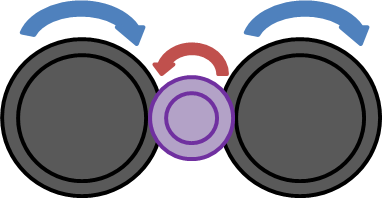
Gears are the most common form of power transmissions. The entire system of gears used to manipulate motor speed, torque or direction is called a gear reduction. For every power transmission using gears, there is, at minimum, a driver gear and a driven gear. A driver gear is the gear that is directly connected to the motor that then “drives” or turns the rest of the system. Driver gears convert torque to force. The driven gear is connected, directly or indirectly, to the driver gear and outputs power to the mechanism. Driven gears convert force to torque. Any gears between a driver gear and a driven gear that have no effect on the total system are called idler gears.
A gear ratio determines what amount of the motor power will be converted to torque with the gear reduction. To find the gear ratio, you need to know the number of teeth (N) or the torque (τ) on both the driver and driven gears, as well as the efficiency of the gears.
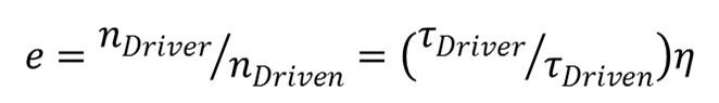
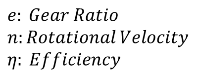
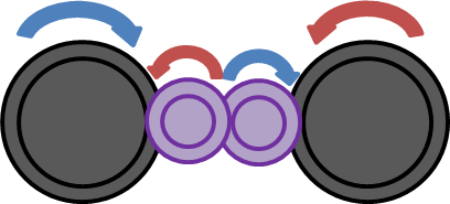
The gear ratio can also be found by multiplying the numbers of all the driver gears together and dividing by the product of the number of teeth on all of the driven gears. For example, in the picture to the right, the yellow gear is a 16 tooth, the red gear is a 38 tooth and the blue gear is a 92 tooth. Therefore the gear reduction would be .174 or 5.747:1. To see the calculation, click here

Remember: A transmission with a small driven gear and a large driver gear will produce low speed and high torque. A transmission with a large driver gear and a small driven gear will produce high speed and low torque.
Change the gear sizes or driver speed to see how the speeds of the idler and driven gear change. Hit the space bar to add a fourth gear on the same axle as the idler. Again, change the variables to see how the system outputs change.
Other Vocab for Gears
Pressure Angle: The angle between the tooth force and gear wheel tangent
Diametral Pitch: The number of teeth divided by the diameter of the gear. This is generally used to classify different gear sizes and types.
Spur Gears
Spur gears are the most common gears. They general consist of a circular disk with equally spaced teeth extending radially to mesh with other spur gears.
Fun Fact – spur gears do not have to be circular. They can be any shape as long as the tooth pattern of one gear is an exact inverse of that of the gear it will mesh with.
A transmission with an odd number of spur gears aligned will have the final driven gear moving in the same direction of the motor. Likewise, an odd number of gears results in the final driven gear moving in the opposite direction of the motor. Generally spur gears are very efficient with η values between .95 and .98.
Worm Gears
Worm gears are a specific type of gear that provide high torque outputs and are not able to be back driven. Worm gear transmissions may have gear reductions of up to 300:1. To determine the gear reduction, you have to divide the number of teeth on the gear by the number of teeth or spirals on the worm. However, because the spiral on the worm is continuous, it acts as one singular tooth. Therefore the reduction is simply a ratio of N:1, where N is the number of teeth on the gear. If the worm has two spirals, then the ratio becomes N:2. It is important to keep in mind that worm gears are generally very inefficient with η values between .25 and .75.
Planetary Gears
Planetary gears are a system in which at least one “planet” gear rotates around a central “sun” gear. Planetary gears are often used in automatic transmissions. Depending on the design of the system, the power input can be from the sun gear, the planet gear, or the ring gear that surrounds the system. If the input comes from the sun gear, then the power output comes from the planet gears and the ring gear stays stationary. If the planets are fixed in place, then the input would still come from the sun, but the output would then come from the ring gear; in this case, the ring gear moves in the opposite direction of the sun gear. When the sun gear is fixed, the power input comes from the ring gear and the power output is the planet gears; this makes the output shaft decelerate in proportion to the output shaft.
Chain and Sprockets
Chain and sprocket transmissions have similar torque and speed properties to gears, but can be used in situations where the motor is located far from the wheel or mechanism. When working with chain and sprocket transmissions, the distance between two of the rollers is called pitch. Chains are rated with two-digit codes. The first digit denotes the pitch of the chain in eighths of an inch. The second digit can be a 0, 1, or 5; a zero denotes a chain as a “roller” chain, a one denotes a “lightweight” chain, and a five denotes a “brushed” chain. Two common chains are #25, with a breaking strength of 875lbs and a working strength of 140lbs, and #35, with a breaking strength of 2100lbs and a working strength of 480lbs.
When using chain and sprocket transmissions, the chain must be wrapped a minimum of 120o around the sprocket. Further, an ideal reduction for a chain and sprocket reduction is 12T to 75T. A larger reduction will lead to losses in efficiency from the chain. A smaller reduction than 12:75 will result in vibrations of the system and excess wear. Finally, it is important to remember that any chain is only as strong as its master link. A master link is able to open in order to add or remove links from the total chain length; because of this it will only withstand up to 70% of the strength of the rest of the links.