ME 3901 Engineering Experimentation
Laboratory IV: Temperature Measurements
· Objectives
· Introduction
· Tasks
· Procedure
· Data for the Report
Objectives
One objective of this laboratory is to develop an understanding of the basic properties of temperature measuring devices; specifically, thermometers, thermocouples, thermistors, and RTDs. One must determine the requirements and techniques to acquire and process them into meaningful numerical representations. An error analysis of the experimental measurements is required for this laboratory.
This laboratory concentrates on configuring various temperature measuring devices (thermometers, thermocouples, RTDs, and thermistors). You will build a few vi programs including a multi-sensor vi. The thermometer will be used as the reference standard to calibrate the other temperature transducers.
There are several tasks required for this multiple session experiment:
1.) Weld (or solder) thermocouples.
2.) Run group-created
3.) Run a multi-channel VI that writes to disk and reads numerous types of temperature transducers.
4.) Calibrate thermocouples, RTDs, and thermistors.
A) Each person solders a thermocouple (approx. the same length as the RTD probe plus wire) and tests it to verify that it works. A preliminary Thermocouple.vi designed by the group must be built to read the temperature. This task requires minor modifications of previous VIs created. Be sure you read the additional information provided via the web for the various transducers: Measure Temperature using Thermocouples is specific to the thermocouples.
Consider the block diagram region that contains the DAQmx-Create Channel Icon and its associated 'show help' description:
![]()
DAQmx - Create Channel Icon listing "AI Voltage" as the input mode.
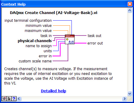
Show Help Identifies the Wiring Tab Functions for this Analog Input Icon
Using the Operator Tool (the hand) on the block diagram, one can change the Analog Input to be Temperature -> Thermocouple instead of Voltage.
![]()
The DAQmx was changed to read a thermocouple instead of voltage
Note that the Show Help changes and it offers different tabs. The three significant differences for our work are the Units, Thermocouple Type and CJC Source. Additionally, when one changes the Icon task (from AI to AO for example), many of the tabs change requiring that old extensions (or tabs) be deleted and new ones created. (Recall: in the Ohmmeter lab, many students could not find the AO channels with the front control browse button. they had to delete the physical channel icon and create it again.)
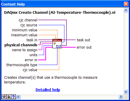
Show Help for Thermocouple Analog Input
Create a constant for the "units" and specify "deg C"; create a constant for the "cjc source" (the cold-junction reference source) and select "Constant Value". Create a constant for the "thermocouple type" and select type "T" and create a control for the cjc value. Use a thermometer to read the temperature of the room and enter that value for the cjc value.

Specify a temperature range of 0 through 100 deg C on your front panel. You should be able to run your vi, measure temperature and record values. To test this initial VI, simply squeeze the thermocouple tightly between your fingers. If the temperature rises, odds are the VI is fine. If the temperature drops, your partner might suspect that you are a vampire, or you've switched the positive and negative connections of the TC.
The front panel could have a thermometer style display instead of the waveform chart or the meter display of your resistor experiment. This initial VI is simply to verify that one can read a TC.
B) Each group must configure and run a VI to test and read a resistance device (a thermistor and an RTD, separately). (Be sure you read the additional information provided via the web for the various transducers: Measure Temperature via Thermistors, is appropriate for this component.) NI provides both a current excitation and voltage excitation thermistor option. We are using the Voltage Excitation technique (i.e. a voltage divider with a known resistor). (See NI discussion of Steinhart-Hart thermistor equation) The thermistor located on the strain-gage plate is an Omega SA1-TH-44004-40-T thermistor. It has 2252 Ohms at 25 degrees C. The following link lists numerous coefficients for the Steinhart coefficients. Both styles of thermistors in the lab (the plate thermistor, and the stainless steel probe thermistor) have a rating of 2252 Ohms at 25 Deg. C. We will read read (and record) resistance and temperature of the probe thermistor to a file for our applications. The following block-diagram and front-panel show a method to read thermistors. Note in this VI there are two button activations: 1) Monitor Transducer True/False Loop and a nested 2) Record to Disk True/False Loop. Frequently when connecting a different resistor into the circuit, the system could report strange results (since the circuit was open, closed, or another transient state). That situation could potentially lock-up the while loop. Therefore, the Monitor Transducer Button was added. The VI adjusts the analog input and output values to keep the transducer self-heating effect low automatically. The Analog Input function was changed to a) Read Multiple Channels AND b) Read Multiple Samples Per Channel (See lower left of block diagram). This feature allows one to rapidly sample a channel (and we subsequently take the average).
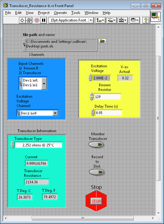
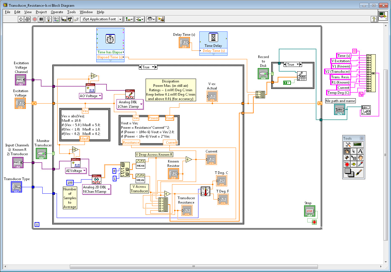
Front Panel and Block Diagram of a VI to Read a Thermistors or RTDs (Using a Voltage Divider option)
Note: the 'cute' Icon at the lower right corner of the loop. It is a sub-VI for our lab.
Spend a little time examining this VI compared to the thermocouple VI you built. Many components from this VI can be used in subsequent designs. One new component is the use of a user sub-VI. Download the Transducer_Resistance.vi and the sub-VI TransducerCalculator.vi Save them on your desktop or folder. Have both VIs in the same location. Wire your thermistor or RTD (as R2) in the following connection schematic.
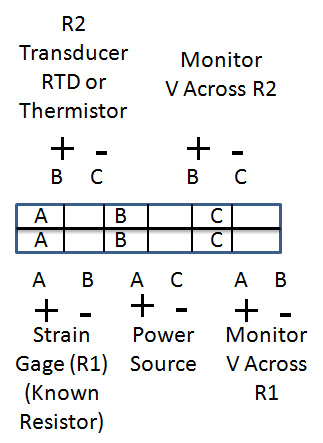
Test your configuration for this voltage divider set-up. Be sure you configured the correct channel specifications in the VI. Run the VI and verify that it reports reasonable temperature values (as yet un calibrated).
C.) Once you are satisfied that it is registering temperature swap out the thermistor and connect the RTD using a 2-wire configuration. That is, treat both black wires as the same. Change the transducer type on your VI and repeat the verification of temperature behavior. (Be sure you read the additional information provided via the web for the various transducers: Measure temperature via RTDs )
This sub-VI has no while loop. There are two required inputs (the Transducer Type and the Resistance). There are two outputs (Temperature in Deg. C and Deg. F). The VI has the following form:
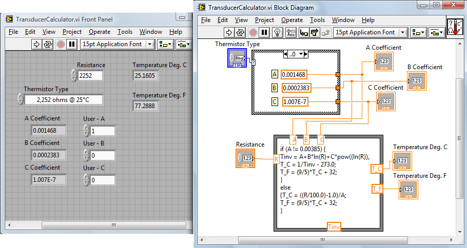
The top select-case node has 4 different situations - 3 thermistor values and 1 rtd coefficient assignment. How was the sub-VI created? Examine the NI help section on sub-VIs. We will discuss this more later.
At this point you have 2 VI programs that record
temperature (a Thermocouple VI and a resistance related transducer for temperature). You have verified that when the probe
temperature increases the
D.) Run a multi-channel VI that can read a thermocouple, a thermistor and an RTD. The VI used in part B and C measured two resistors (one known, the other a transducer). Now we need to measure 3 resistors in series: i) a known resistor (used to determine the current in the series loop), ii) the thermistor probe, and iii) the RTD probe. Additionally we need to measure a thermocouple. The resistor measurements can all be done with a similar "DAQmx" icon as in part B. The thermocouple needs a VI similar to part A, which would create a conflict of resources error if they both try to read simultaneously. Therefore, a sequence loop is required, similar to that used in the strain gage lab. In that previous lab, there were two different ranges required (one for excitation circa 5 Volts and another for the millivolts generated across bridge nodes C-A). For the temperature lab we are reading temperature via a thermocouple and resistance which requires separate "DAQmx" configurations. Download the Multi-Channel-Transducer.vi Save it on your desktop or folder in the same location as the previous VI since this one also uses the TransducerCalculator sub-vi.
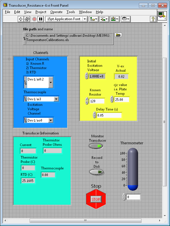
Front Panel with Additional Resistance Measurements Included
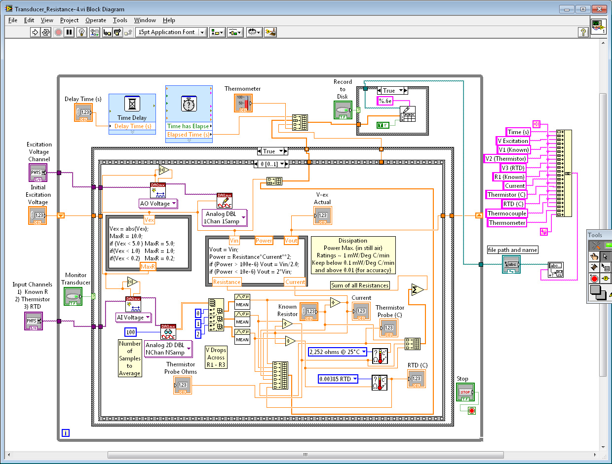
Block diagram with Additional Resistance Measurements Included
Sequence "Zero" has recorded voltage drops across 3 resistors, determined the current passing through them, determined their resistance values (save the known resistor), and calculated their temperatures. All pertinent data has been added to the build array for storage. As discussed in class, the thermocouples VI is relatively simple in comparison. It is constructed in Sequence "One" as shown below. Additionally, the thermometer control needs to be recorded to disk so that all transducers can be calibrated. This has been added as the last entry.

Block diagram for Thermocouple Measurements Included
E.) When operational you should be able to scan multiple channels and record the temperature values (and time) to disk using the VI developed in D. A possible connection strategy might be as follows:
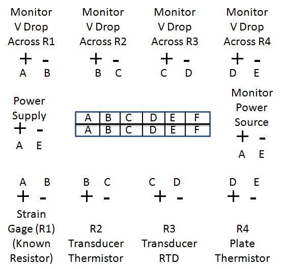
Wiring diagram for Resistor Components
Note: the thermocouples are connected directly to an AI channel. It is assumed that the connection location is similar in temperature as that of the strain gage plate. The transducers (RTD, thermistors, and T/Cs) need to be calibrated. Place the transducers in multiple temperature sources; an ice bath, an intermediate-temp baths, and a hot water baths for calibration purposes. Calibrate each transducer. Use a thermometer as the reference value for the source. This sequence must be repeated multiple times such that you have at least 7 different temperature locations that span the temperature range. You do not need to change the water sources. As you loop around them, their temperature values will change, but so will your thermometer input (Control). Making multiple loops will give you different temperatures for which you will have data. Remember, as the lab continues the cold and hot sources will drift towards room temperature. Your primary concern is to adjust the thermometer for the current temperature reading prior to recording to disk. TO REDUCE system crashes, one might consider stopping the vi after each temperture (IF SO, change the name of the file before restarting). Alternately, turn off the "Monitor Transducer" switch in addition to toggling the write to disk button.
F.) Verify that your data was recorded and both partners have all data and VIs. At a later time, within Excel determine a regression for each transducer. Display in your lab write-up a graph of each transducer showing the regression coefficients, the goodness of fit and the data plotted. As part of your write up, be sure to include images of your panel and diagrams, information about your calibration procedure summarized from your excel files (not the 1000s of points printed out!).