The electrical analog of the damped mass-spring oscillator is the LCR circuit. The inductance L acts as the "inertia" of the system, while the reciprocal of capacitance 1/C = V/Q acts as the "force constant", in this case voltage per unit charge, which is a kind of "electrical pressure". Not surprisingly, the resistance R serves as the source of damping. In this lab you will measure and plot the capacitor voltage V(t) and perform a curve fit to an exponentially damped sinusoidal function to obtain the frequency ωd and damping factor γ. You will compare these measured values to calculated values, and use γ to calculate the resistance R in the circuit. Note that the circuit has no resistor. The reason is that the inductor, capacitor, and wire each have small resistances that sum to give a total circuit resistance of a few ohms. The curve fitting process can be fussy, but it is a great way to become familiar with the effects of adjusting the various parameters A, γ, ωd, φ, and voffset.

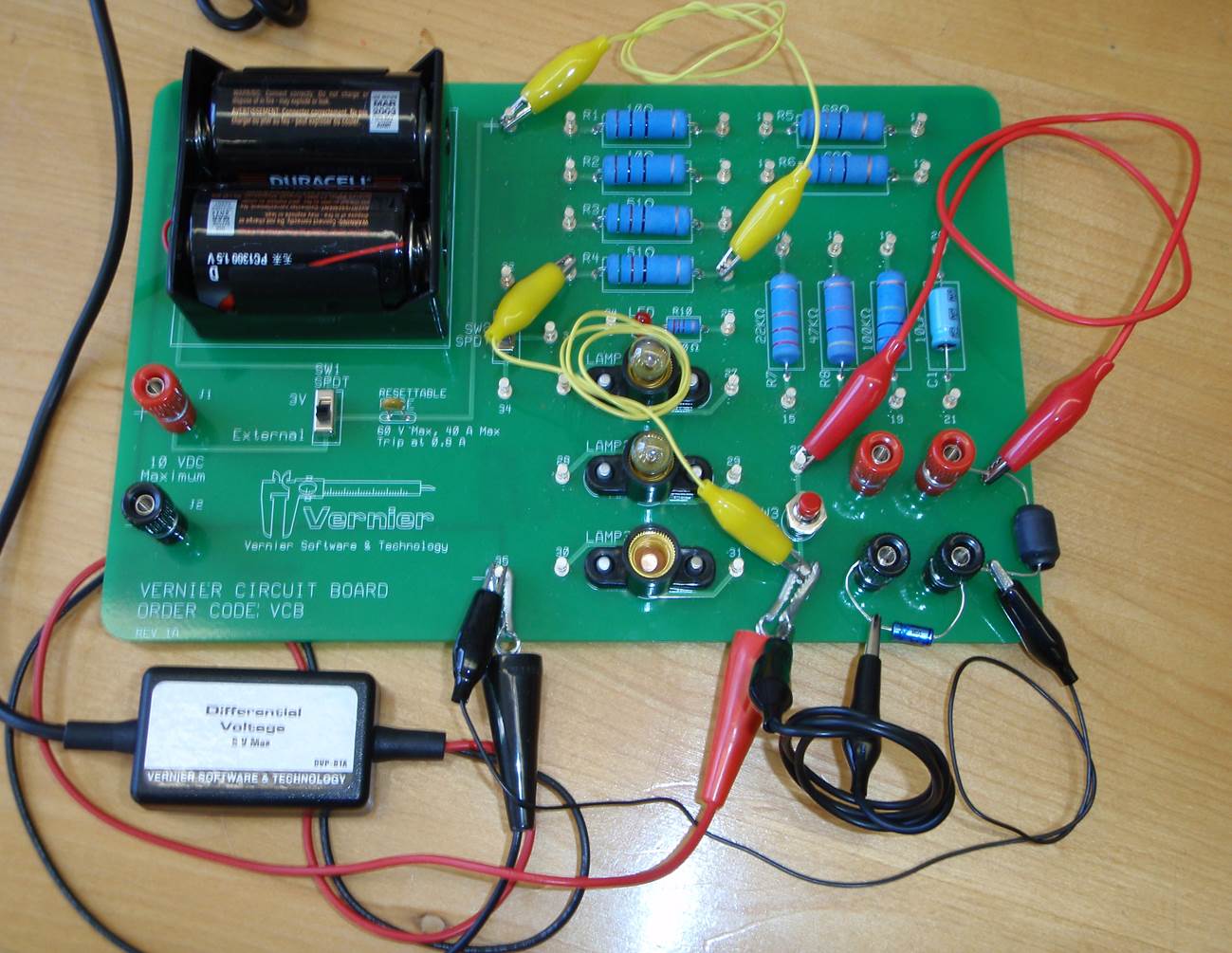
Attach an external voltage source to the External VDC posts, and adjust the voltage to 3V. Make sure the Power On/Off switch is in the Off position (NOT set to External). Assemble the circuit as shown above. The positive side of the power source, marked POS, is routed through a 51 Ω resistor via yellow leads, to the lower post of the Push Button. The capacitor C is electrolytic and is sensitive to polarity, therefore take care that the dimpled end of the capacitor, the positive end, is attached to the lower post of the Push Button. For this, use a low-Ω lead to attach the capacitor to the Push Button. The inductor L is not sensitive to polarity, and may be attached either way. Use another low lead to attach one end of the inductor to the other post of the Push Button. To complete the charging circuit, attach the other end of the inductor to NEG (small black lead at bottom). Attach the Venier (R) Differential Voltage probes as shown, so that the capacitor voltage may be read by Logger Pro.
Open the Logger Pro File and zero the voltage. Charge the capacitor to by setting the Power On/Off switch to External. Click on Collect, and do the following two steps in quick succession: flip power off and press the Push Button for a moment. By pressing the Push Button, the circuit is completed, the capacitor discharges through the inductor, and damped oscillation ensues. The template is set to trigger data collection the moment voltage drops below 2.9V. The template also sets the voltage sampling rate to 50,000 samples per second, and the collection period to 0.01 seconds.
Once you have obtained a decent plot, perform a manual curve fit to the exponentially damped sinusoid. The parameters A, B, C, D, and E are, respectively, the parameters A, γ, ωd, φ, and voffset in

Enter the values as follows. Set A = V(t = 0), the first data point. Set E = V(t = 0.00998), the last data point. Start with a damping factor of B = 10,000 rad/s, a frequency C = 18,000 rad/s, and initial phase D = 0.5. To improve the fit, adjust B, C and D. Be persistent, keep adjusting the parameters, and try to reduce the RMSE of the fit to 0.15 or less. The better the fit, the lower the RMSE, and the better will be your measured values of ωd and γ.
Read the fit parameters and record the damped oscillation frequency ωd and the damping factor γ. Use the measured value of γ and the manufacturer's nominal value of inductance L = 1 mH to calculate the circuit resistance R.
Using the nominal values of L and C = 3.3 μF, calculate ω0. How well does this value agree with the measured values of ωd and γ? Manufacturers specify a percent tolerance for components, typically in the range 5 to 20%. What can you conclude about the product LC?
Connect a resistor in the range of 3 to 50 Ω between the inductor and the upper post of the Push Button. Use the low-Ω lead to accomplish this. Do a Google search on "resistor color code" to learn how to read the values of your resistors from their color bands. What is the total R resistance of your circuit? Using the corrected value of LC, calculate the new frequency ωd and damping factor γ. Charge and operate the modified circuit, obtain V(t) and perform a curve fit. Read the fit parameters and record the damped oscillation frequency ωd and the damping factor γ. How well do these agree with the calculated values?