PH 1120 Lab 4: Resistors and Lightbulbs
Objectives
In this lab we will measure the resistances of the following:
- Individual resistors;
- Combinations of resistors in series and parallel;
- A light bulb.
Procedure
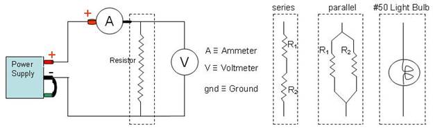
- Build the circuit as shown for measuring resistance.
- Measure the resistance of the 51Ω resistor (R1):
- Open the Linear Resistor Logger Pro File.
- Starting from 0 volts, record a set of points (we ask for nine) for voltages ranging from 0 to 4 volts. Hint: These voltages do not need to be exactly placed every 0.5V; fairly close will work fine.
- Make a linear fit to the voltage/current slope to extract resistance.
- Repeat step 2 for the 68Ω resistor(R2), the two resistors in series (Rs), and the two resistors in parallel (Rp).
- Repeat step 2 for the #50, round-headed light bulb, with a couple changes:
- As it is nonlinear, gather more (we recommend 0, 0.1, 0.2, ..., 0.6, 0.8, 1.0, 1.25 4.0) points along the V-I curve.
- Record the voltage at which the bulb just barely begins to glow.
- Use a tangent line to determine the resistance at various points along the curve, recording the resistance and voltage at which that resistance occurs for (1) the minimum resistance, (2) the maximum resistance, and (3) the point where the resistance changes most rapidly.
Data Checklist
- Experimental measurements of R1, R2, Rs, and Rp.
- Theoretical calculations of Rs and Rp based on R1 and R2.
- The voltage at which the lightbulb first glows.
- The minimum/maximum/fastest-changing resistances of the light bulb.
Logger Pro Files and Lab Report
Back to PH 1120 Labs
Back to Main Page