Analog Lab Virtual Tour
Welcome to The Analog Lab Virtual Tour!
First a word of thanks to our sponsors:
- The National Science Foundation
- Allegro Microsystems
- Analog Devices Semiconductor
- BAE Systems
- Texas Instruments
- Agilent
- Tektronix
- The Joseph Samuel Satin Foundation
- WPI
Their generous support has been essential to the development
of The Analog Lab as a resource for research in analog and
mixed signal microelectronics.
Now, on with the tour! Our first stop is the ...
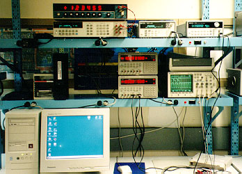
Precision DC Instrumentation Station

This lab station features instruments that allow extremely
precise measurement of DC and low frequency characteristics.
The key instruments are:
- Hewlett Packard HP3458A Multimeter
- This DVM measures voltage, current, or resistance to 8-1/2 digit
precision (that's tens of nanovolts)
- Data Precision DP3200 DC Calibrator
- The "volt box" provides a precise
output from -10V to +10V, controllable in
10uV increments
This station also includes
-
HP33120 Arbitrary Waveform Generator
- Allows generation of standard waveforms (sine, square, triangle,
etc.)
as well as arbitrary waveforms up to 15MHz.
-
HP53181A RF Counter
- Provides 10-digit frequency measurement capability for
inputs up to 3 GHz
- HP54601A Oscilloscope
- This scope, a four-input member of the HP54600 family of digital
oscilloscopes, has an input bandwidth of 100 MHz.
- Tektronix PS2520G Power Supplies
- Each supply providing current-limited
outputs up to +6V and +/-20V, with output voltage and current limit
digitally displayed and adjustable either by the front panel keypad
or in software over the IEEE-488 bus.
- Pentium PC
- Configured with hardware and software for control of all
lab instruments over the IEEE-488 bus.
Our next stop, one bench over to the right, is the ...
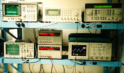
High Speed Time / Frequency Domain Measurement
Station


This bench features instrumentation for measurement
of very high speed circuitry, and characterizing performance
in both the time domain and frequency domain. The key instruments are:
- Tektronix
11801C Digital Scope / Communications Signal Analyzer
- This instrument allows acquisition of waveforms with frequency
content up to 25 GHz with time domain resolution of one picosecond. In
The Analog Lab, this capability is used for time
domain measurements
of oscillator jitter.
- Tek TDS784C Digital Oscilloscope
- This scope has four input channels and can provide real time
sampling
at 1GHz. Higher sampling rates for repetitive waveforms can be achieved
with equivalent time sampling.
- Hewlett Packard HP8648D Low Phase Noise RF Signal Source
- When testing the phase noise of a Phase Locked Loop (PLL), the
PLL
must be provided a stable clock to lock onto - otherwise, you don't
know if the noise you see at the PLL output is from the PLL or the
input
source. This signal source provides a very low phase noise output
at frequencies up to 4 GHz.
- HP8560E Spectrum Analyzer
- This instrument allows frequency domain measurements over a range
of 30Hz to 2.9GHz. In The Analog Lab, this capability is used for measurements
of oscillator phase noise, which is the frequency domain
counterpart of time domain jitter.
Other equipment available at this station:
- Wavetek Model 395 Arbitrary Signal Generator
- This arbitrary signal generator provides outputs up to
50MHz with moderate phase noise performance.
- HP54645A Mixed Signal Oscilloscope
- This scope allows simultaneous acquisition of two analog
waveforms
(bandwidth up to 100MHz) and 16 bits of digital data. This scope is
especially useful for testing mixed signal circuits, to observe the
time domain relationship between analog and digital signals.
- Tektronix
PS2520G Power Supplies
- Each supply providing current-limited
outputs up to +6V and +/-20V, with output voltage and current limit
digitally displayed and adjustable either by the front panel keypad
or in software over the IEEE-488 bus.
The instrumentation at this bench is also linked to the PC over
the IEEE-488 bus, allowing automation of experiments and data
collection.
For our next stop, let's take a look at the 11801C scope ...

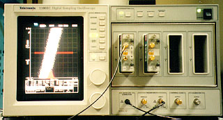
This photo shows the 11801C being used to measure the jitter
of a phase-locked loop. The display is "zoomed in"
on the threshold crossing of the PLL output clock, with the time base
of the 11801C locked to the PLL input clock. Ideally (with
no jitter), the output would be a single rising edge waveform.
In reality (in the presence of jitter), as can be seen from the
11801C display, the threshold crossing appears "fuzzy" due to
the superposition of many waveforms which cross the threshold
at different times due to jitter. The 11801C compiles a histogram
of the threshold crossing times, and measures the standard
deviation of the histogram, which is a quantitative measure of
the jitter.
The corresponding measure in the frequency domain is phase noise.
For a closer look, lets step up to the HP8560E spectrum analyzer ...

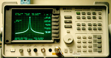
This photo shows the HP8560E measuring the spectrum of the
PLL output clock. The clock is an emitter-coupled logic (ECL)
waveform, which has harmonic content at multiples of the
155.52MHz fundamental. To measure phase noise, however,
the spectrum analyzer is "zoomed in" to a frequency range near
155.52MHz. The measurement shown was taken with a
center frequency of 155.52MHz and a span of 1MHz.
Ideally (no phase noise), the spectrum would be an impulse at
155.52MHz
(as every good signals-and-systems student knows). In reality (in
the presence of phase noise), the spectrum is broadened and there
are "skirts" of phase noise power on either side of the central peak.
The HP8560E measures the magnitude of this noise power relative to the
power in the fundamental; the result in dBc ("decibels relative to
carrier")
is a measure of phase noise.
We've Got Workstations, Too
The Analog Lab is equipped with multiple Linux PC workstations, which
are all networked
to the ECE department server which is loaded with an assortment of CAD
tools
for circuit design and simulation.
This concludes our Virtual Tour of The Analog Lab. Thanks!


