Date
|
Lec
|
Handouts
|
Annotations
|
Mon
Mar 16
|
1 |
Course
Information
Academic Honesty
Course Outcomes
Lecture Outline Term Calendar
Weekly Help Schedule
KVL-KCL Review
Nodal
Analysis Example
Superposition
Review (from 2019)
Thevenin's
Theorem |
Motivation: Digital Audio
Signal Chain
2 Big System Questions: How Big? How Fast?
|
Tue Mar 17 ☘
|
2
|
Lecture Overview |
Why Amplify? | Transducers |
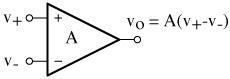
General Amplifier Model
Ideal Op-Amp
|
Annotated
Slides
|
Thu Mar 19
|
3
|
Open
Loop vs. Closed Loop Gain Comparison
LM741 Data Sheet
|
Annotated Slides
|
Fri Mar 20
|
4
|
Lecture Overview | Blank
Slides
|
Annotated Slides

|
Mon Mar 23
|
5
|
Lecture Overview | Blank
Slides
Transfer
Function Review
Bode Plot Guide
Step Response of 1st
Order System
Bandwidth - Risetime
Relationship
Op-Amp
as a
Classical Feedback System
Complex Number Review
|
Lecture Overview |
"Language" of Transfer Function |
Annotated
Noninverting, Inverting Gain Analysis Handout
Annotated
Noninverting Gain Handout for
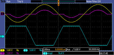
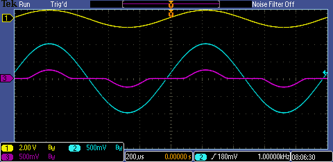
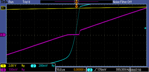
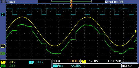
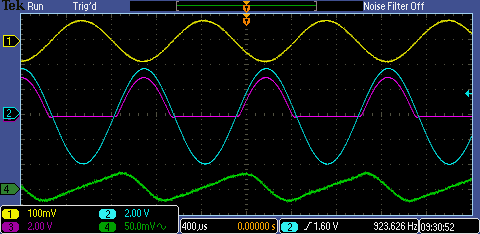
Noninverting Gain = +100 Amplifier Scope Photos:
f = 100
Hz 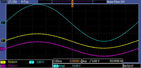
|
vI |
vO |
v- |
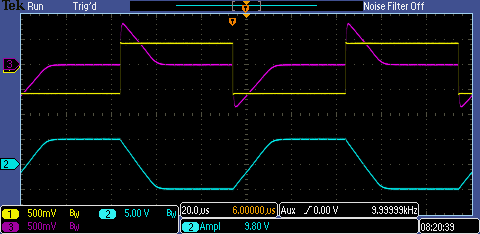
f =
1kHz  |
vI |
vO |
v- |
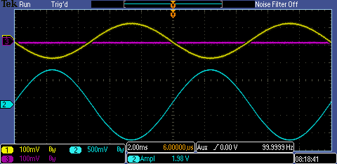
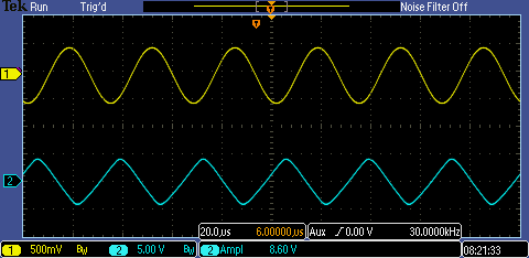
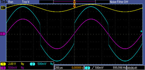
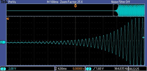
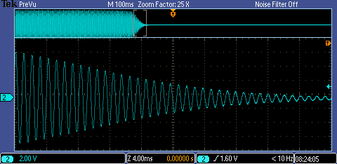
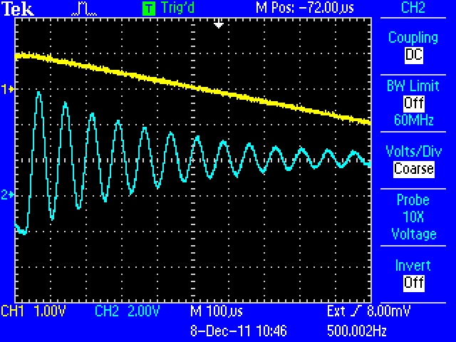
f = 10
kHz 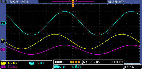
Note reduced gain to output |H(10kHz)| = 75
Phase shift at output
Inverting input v- unable to track v+=vI |
vI |
vO |
v- |
Annotated
Transfer Function Review Handout (pp. 1-6)
|
Tue Mar 24
|
6
|
Lecture Overview
Bode Plot Form |
Closed Loop Bandwidth |
Completed Bode Plot Form
Annotated
Transfer Function Review Handout (pp. 7-10)
Annotated
Step Response, Bandwidth - Risetime handouts
|
Thu Mar 26
|
7
|
Lecture Overview | Amplifier
Design Example
Op-Amp
Error Matrix
LF356 Op-Amp Data Sheet |
Annotated
"Op-Amp as a Classical Feedback System"
Annotated Design
Example Slides
Annotated
Error Matrix
|
Fri Mar 27
|
8
|
Lecture Overview
Offset, Bias Current
DC Errors
Slew Rate Limiting
Links to Op-Amp Selection Guides
|
Annotated Slides |
Mon Mar 30
|
9
|
|
Annotated Slides
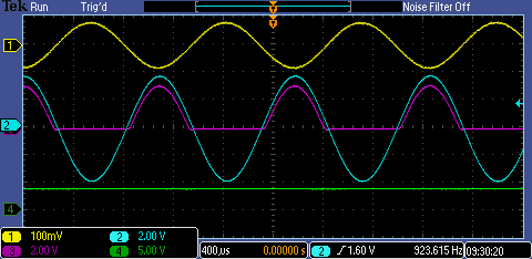
Annotated
Inverting Gain Handout for
Inverting Gain = -10 Amplifier Scope Photos:
|
Tue Mar 31
|
10
|
|
Annotated Slides
|
Thu Apr 2
|
11
|
Lecture Overview | Lab 2
Circuits
LM311 Comparator Data Sheet
|
Annotated Slides
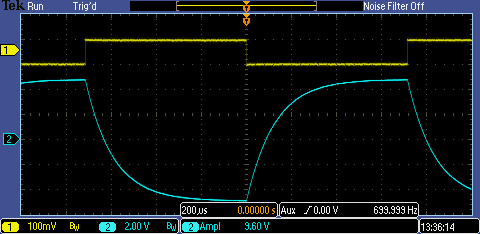
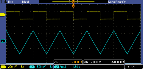
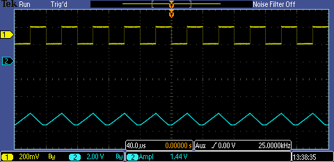
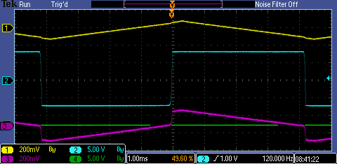
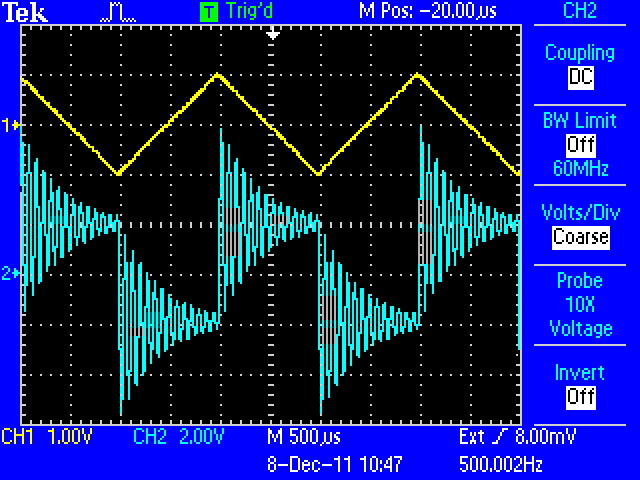
Active
Filter, Integrator Square Wave response Scope Photos:
Annotated
Push-Pull Amplifier Handout for Scope Photos:
|
Fri Apr 3
|
12
|
Lecture Overview |
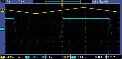
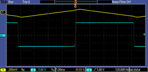
Comparator, Schmitt Trigger
|
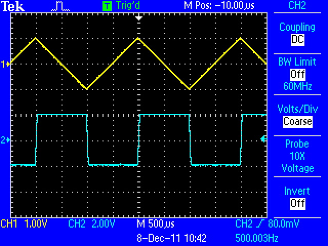
Annotated
Comparator | Schmitt Trigger Handout for Scope Photos:
|
Mon Apr 6
|
13
|
|
Annotated Slides
|
Thu Apr 9
|
14
|
Lecture Overview | Handout
Slides
LM555 Block
Diagram
LM555 Data Sheet |
Annotated Slides
|
Fri Apr 10
|
15
|
Lecture Overview | Handout
Slides
|
Annotated Slides
|
Mon Apr 13
|
16
|
Lecture Overview | Handout
Slides
Lab 4 Circuits
Lab 4
Circuits pSpice handout |
Annotated Slides
Annotated
Simulation Figures
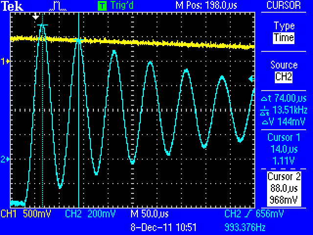
Annotated
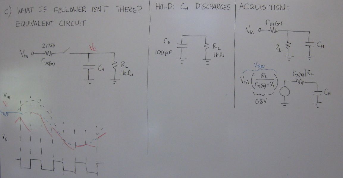
Sample-and-Hold Circuit for Scope Photos:
|
Tue Apr 14
|
17
|
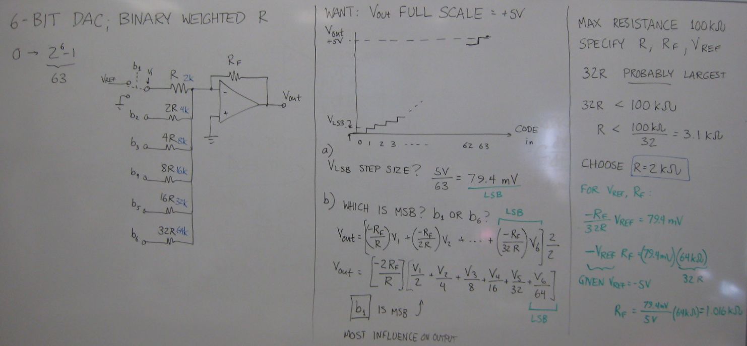
D/A converters
Binary Weighted R
R-2R Ladder |
Annotated Slides:
2:1 Analog
Multiplexer | Sample-and-Hold Simulations | D/A Converter
|
Thu Apr 16
|
18
|
s-plane Notes
|
D/A Converters
Annotated s-Plane
Notes
|
Fri Apr 17
|
19
|
Filter
Type and
Specification
Comparison of
Filter Family Transfer Functions
Sallen and Key Circuit
5th order
Butterworth Design Example
3rd order
Butterworth Design Example
|
Annotated Slides:
Filter types and
families
Sallen and Key circuit
Butterworth filter design examples
Exam 2 preview examples
|
Fri Apr 24
|
20
|
Finding Loop Gain /
Stability Analysis Handout
Notes
on Textbook Stability Reading (6th
ed.)
|
Annotated Slides
Differentiator Scope Photos:
|
Mon Apr 27
|
21 |
Lecture Overview | Intuitive
Stability
Practical Differentiator
|
Annotated Slides: Finish
Stability Analysis from Lecture 20 |
Practical Differentiator
|
Tue Apr 28
|
22
|
Lecture Overview | Wien
Bridge Oscillator
MATLAB for phase margin cases
|
Annotated Slides:
Finish
Practical Differentiator
Wien Bridge
Oscillator
Wien Bridge (no AGC) waveforms:
|
Thu Apr 30
|
23
|
Lecture Overview | Phase
Margin Examples
|
Annotated Slides
Annotated
AGC Circuit for Scope Photos:
BONUS
CONTENT!!! Phase Margin / Pole Angle Relationship |
| Fri May 1 |
24
|
Lecture
Overview
|
Annotated
Slides
|
Mon May 4
|
25
|
Lecture Overview
ADC Overview
Flash ADC
Ramp ADCs
Successive Approximation ADC
|
Annotated Slides
|
Pre-Exam-3
Help Session
|
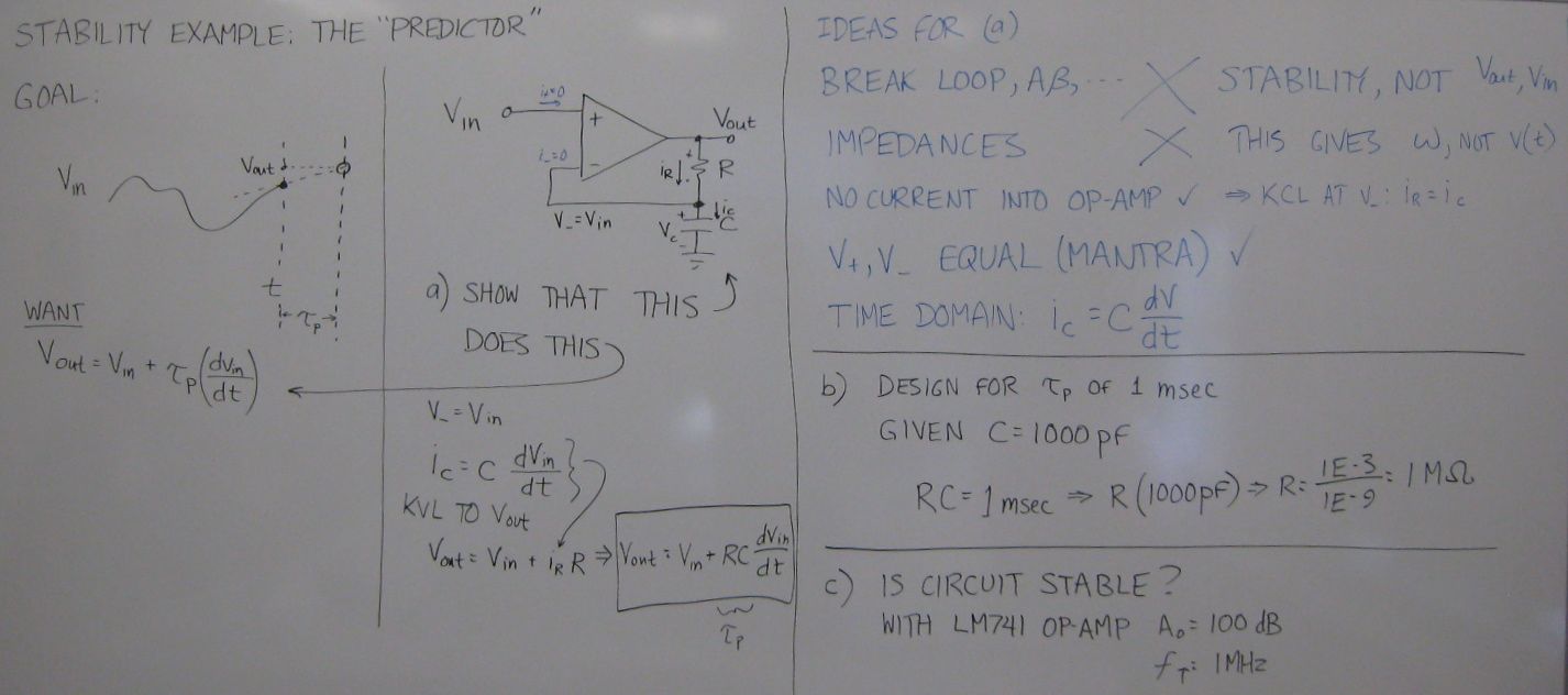
Example problems:
"Predictor" Circuit: Input-Output
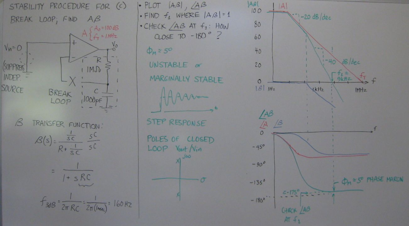
Relationship | Stability
Analysis
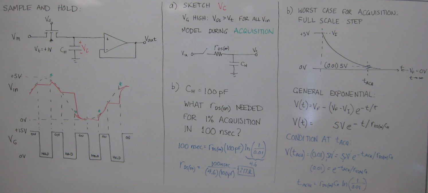
Sample-and-Hold: Waveforms
| Acquisition | What if
Op-Amp Isn't There?
D/A
Converter
|


