 Preface: Will it Fall Down?
 Author: Brigitte Servatius
Publisher: The GEOMAP Project, COMAP, 1994.
(The GEOMAP project seeks to provide materials for high school teachers and students to help the bridge the gap from high school geomtry to modern mathematics and applications.)
 Preface: Will it Fall Down?
The first rule in surviving an earthquake is get out of doors. This rule is particularly disconcerting for us in our high technology society. Indoors we find not only shelter from the wind and the rain, but we find also the first aide kit, running water, the telefax, the radio, and the TV. If we are told, ``Don't go indoors and don't drive your car,'' we are nearly helpless. Even after a mild earthquake we do not feel safe and wonder whether the buildings and bridges have been damaged.
Sometimes buildings collapse without an earthquake. This nearly happened in Paris when the Cathedral of Notre Dame was constructed. It became clear that the walls had so many large windows that they were not strong enough to support the weight of the roof. Making the windows smaller was out of the question, since the light from the huge stained glass windows was critical to the overall design. In the end the walls had to be supported from the outside by huge stone braces called {\em buttresses}. Here the problem was in the strength of the materials, rather than the shape of the building. If the walls could have been stronger, or the roof could have been lighter, the buttresses would not have been necessary.
The construction for a new building is now often started by putting up a shell of steel girders. Every few years we read that such a shell has suddenly collapsed. On the news there will be film of a twisted heap of metal that, just a few hours ago, was a towering framework of brand new steel girders. Unlike the Cathedral of Notre Dame, the problem is not the strength of the materials. Large frameworks of steel are routinely constructed. Here the problem is usually in the arrangement of the girders. The framework has {\em folded up} at the joints.
In 1984 a two year project was begun to completely renovate the Statue of Liberty for its centennial. In order to complete the work on the outside of the statue, a scaffolding of rods had to be constructed which eventually completely enclosed the statue. The scaffolding could not lean against the weakened statue, and so had to be totally free standing, and had to be sturdy enough to withstand the wind and the storms of New York Harbor. It was an engineering feat in itself - the largest freestanding scaffolding ever constructed.
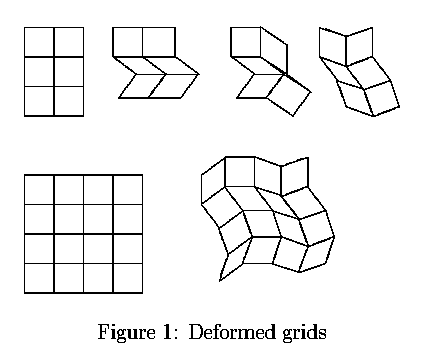
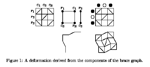
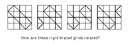
Inside the statue of Liberty, you find a truly 2-dimensional grid such as we will study. Miss Liberty's dress is braced by vertical and horizontal rigid bars, which are bolted together. The bars are not straight, they follow the lines of the dress, but that does not change the mathematics. The figure below shows a typical arrangement of such bars.
Steel girders are attached to one another by rivetting and welding. The rivets and the welds are very strong, but they have two different jobs to do. One job is to keep the two pieces of steel attached together. The other job is to keep the two pieces from twisting at the joint. The first job is much easier than the second, as anyone on the wrestling team can verify - if you grab someone's arm, then it is much easier to keep him from pulling away than to prevent him from twisting in your grasp. Carpenters know this as well. If you nail the ends of two ordinary boards together at a joint, then it should take several hundred pounds of force to break the bond, usually by snapping the nails or splitting the wood. On the other hand, it is not nearly so hard to bend and twist the joint since that can be done by only bending and twisting the nails. One reason this is so easy is that the two boards each act as levers with respect to the joint.
Since a simple joint does a poor job of fixing angles, when analyzing the rigidity of a framework, it is safer to simply assume that the joints prevent the bars from separating, but are completely flexible with regard to twisting and turning. Such a joint is called a {\em ball joint.} A familiar example of a ball joint is the joint in your shoulder, which is designed to allow your arm to twist easily. If the joint fails then the bones come apart and the shoulder is dislocated. You also have a ball joint in your knee, however this ball joint is only $2$-dimensional, and resists twisting from the side, the source of numerous sports injuries. Later we will learn about the rigidity of mechanical ball jointed bar frameworks.
Some figures from the tex:.


